Toyota Tacoma (2015-2018) Service Manual: System Diagram
SYSTEM DIAGRAM
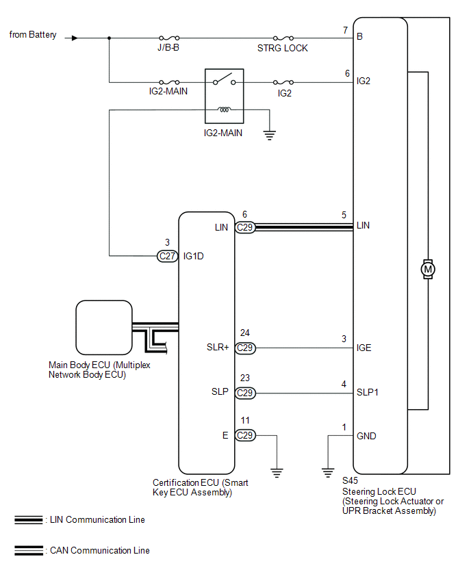 Circuit Description
|
Component |
Outline |
|---|---|
|
Steering Lock ECU (Steering Lock Actuator or UPR Bracket Assembly) |
|
|
Certification ECU (Smart Key ECU Assembly) |
|
 System Description
SYSTEM DESCRIPTION
1. UNLOCK OPERATION CONDITIONS FOR STEERING LOCK
(a) When the following condition is met, the unlock operation is performed.
The engine switch is on (ACC) or on (IG).
H ...
 How To Proceed With Troubleshooting
CAUTION / NOTICE / HINT
HINT:
Use the following procedures to troubleshoot the steering lock system.
*: Use the Techstream.
PROCEDURE
1.
VEHICLE BROUGHT ...
Other materials:
Utility
UTILITY
NOTICE:
If the forward recognition camera has been replaced with a new one or
the windshield glass has been removed and installed, it is necessary to
perform Forward Recognition Camera Axis Adjustment. If the system is turned
on without performing Forward Recognition Ca ...
Yaw Rate Sensor Circuit (C1AA4,C1AA5)
DESCRIPTION
The forward recognition camera receives vehicle stability signals from the yaw
rate and acceleration sensor (airbag sensor assembly). If the yaw rate and acceleration
sensor (airbag sensor assembly) detects an abnormal yaw rate sensor signal or yaw
rate sensor power supply voltage ...
Display does not Dim when Light Control Switch is Turned ON
PROCEDURE
1.
CHECK IMAGE QUALITY SETTING
(a) Display the "Display Settings" screen.
(b) Turn the light control switch to the tail or head position.
(c) Check if "Day Mode" on the display adjustment screen is on.
OK:
"Day Mode" sett ...
