Toyota Tacoma (2015-2018) Service Manual: Noise Filter(for 2gr-fks)
Components
COMPONENTS
ILLUSTRATION
Removal
REMOVAL
PROCEDURE
1. DISCONNECT CABLE FROM NEGATIVE BATTERY TERMINAL
2. REMOVE V-BANK COVER
(See page .gif) )
)
3. REMOVE AIR CLEANER ASSEMBLY
(See page )
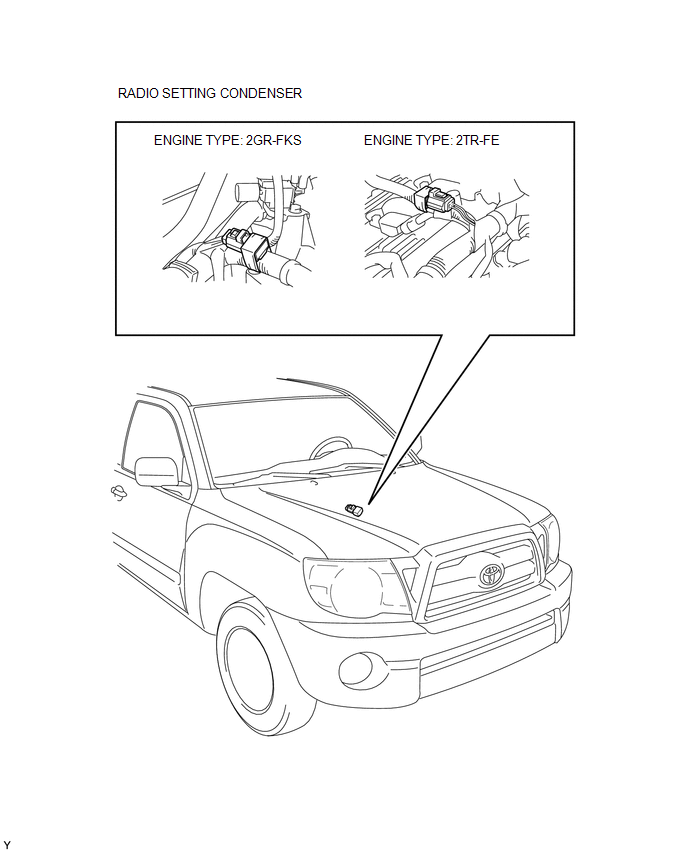
4. REMOVE RADIO SETTING CONDENSER
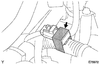
(a) Disconnect the connector.
(b) Remove the tape and the radio setting condenser.
Installation
INSTALLATION
PROCEDURE
1. INSTALL RADIO SETTING CONDENSER
.png)
(a) Connect the connector.
(b) Wind new vinyl tape around the hose and install the radio setting condenser.
2. INSTALL AIR CLEANER ASSEMBLY
(See page .gif) )
)
3. INSTALL V-BANK COVER
(See page )
4. CONNECT CABLE TO NEGATIVE BATTERY TERMINAL
Torque:
5.4 N·m {55 kgf·cm, 48 in·lbf}
 Microphone Amplifier
Components
COMPONENTS
ILLUSTRATION
*A
w/o Sliding Roof
*B
w/ Sliding Roof
*1
TELEPHONE MICROPHONE ASSEMBLY
-
...
 Noise Filter(for 2tr-fe)
Components
COMPONENTS
ILLUSTRATION
Removal
REMOVAL
PROCEDURE
1. DISCONNECT CABLE FROM NEGATIVE BATTERY TERMINAL
2. REMOVE AIR CLEANER ASSEMBLY
(See page )
3. REMOVE RADIO SETTING COND ...
Other materials:
Dtc Check / Clear
DTC CHECK / CLEAR
CHECK DTC
(a) Connect the Techstream to the DLC3.
(b) Turn the ignition switch to ON.
(c) Turn the Techstream on.
(d) Enter the following menus: Chassis / LKA/LDA / Trouble Codes.
(e) Check for DTCs.
Click here
CLEAR DTC
(a) Connect the Techstream to the DLC3.
(b) Turn ...
Sliding Roof does not Move by Operating Sliding Roof Control Switch
DESCRIPTION
The sliding roof ECU (sliding roof drive gear sub-assembly) receives slide and
tilt signals when the sliding roof switch is operated and drives its built-in motor.
WIRING DIAGRAM
CAUTION / NOTICE / HINT
NOTICE:
Inspect the fuses for circuits related to this system before ...
Test Mode Procedure
TEST MODE PROCEDURE
1. TEST MODE PROCEDURE (for Using Techstream)
HINT:
If the ignition switch is turned from the ON to the ACC or LOCK position
during test mode, DTCs related to the signal check function will be cleared.
During test mode, the skid control ECU (master cylinder ...
