Toyota Tacoma (2015-2018) Service Manual: Removal
REMOVAL
PROCEDURE
1. REMOVE FRONT DOOR SCUFF PLATE LH (for Double Cab)
Click here .gif)
2. REMOVE FRONT DOOR SCUFF PLATE LH (for Access Cab)
Click here
3. REMOVE COWL SIDE TRIM BOARD LH
Click here
4. REMOVE INSTRUMENT CLUSTER CENTER FINISH PANEL SUB-ASSEMBLY
Click here
5. REMOVE INSTRUMENT CLUSTER FINISH PANEL ASSEMBLY
Click here
6. REMOVE INSTRUMENT PANEL LOWER FINISH PANEL SUB-ASSEMBLY
Click here
7. REMOVE NAVIGATION RECEIVER ASSEMBLY WITH BRACKET (w/ Navigation System)
Click here
8. REMOVE RADIO AND DISPLAY RECEIVER ASSEMBLY WITH BRACKET (w/o Navigation System)
Click here
9. REMOVE AIR CONDITIONING CONTROL ASSEMBLY
|
(a) Disengage the 8 clips. |
|
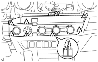
(b) Disconnect the connectors to remove the air conditioning control assembly.
10. REMOVE ENGINE SWITCH
Click here
11. REMOVE TRANSFER POSITION SWITCH (for 4WD)
Click here
 Installation
INSTALLATION
PROCEDURE
1. INSTALL TRANSFER POSITION SWITCH (for 4WD)
Click here
2. INSTALL ENGINE SWITCH
Click here
3. INSTALL AIR CONDITIONING CONTROL ASSEMBLY
(a) Connect the connectors.
...

Other materials:
Precaution
PRECAUTION
1. IGNITION SWITCH EXPRESSIONS
(a) The type of ignition switch used on this model differs according to the specifications
of the vehicle. The expressions listed in the table below are used in this section.
Expression
Ignition Switch (Position)
Engine ...
Speed Signal Malfunction (B15C2)
DESCRIPTION
The navigation receiver assembly receives a vehicle speed signal from the combination
meter assembly and information from the navigation antenna assembly, and then adjusts
the vehicle position.
The navigation receiver assembly stores this DTC when the difference between
the speed ...
Open or Short Circuit in Back Camera Signal (C1622)
DESCRIPTION
This DTC is stored if the radio and display receiver assembly*1 or navigation
receiver assembly*2 judges as a result of its self check that the signals or signal
lines between the radio and display receiver assembly*1 or navigation receiver assembly*2
and the rear television camer ...
