Toyota Tacoma (2015-2018) Service Manual: Installation
INSTALLATION
CAUTION / NOTICE / HINT
HINT:
- Use the same procedure for both the RH and LH sides.
- The procedure described below is for the LH side.
PROCEDURE
1. INSTALL FRONT SHOULDER BELT ANCHOR ADJUSTER ASSEMBLY
|
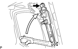
(a) As shown in the illustration, engage the 2 guides to install the front shoulder belt anchor adjuster assembly with the bolt. Torque: 42 N·m {428 kgf·cm, 31 ft·lbf} |
|
2. INSTALL FRONT SEAT OUTER BELT ASSEMBLY
|
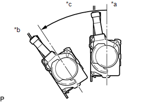
(a) Check the angle of inclination required to lock the retractor. Text in Illustration
(1) When the inclination of the retractor is 15° or less, check that the belt can be pulled from the retractor. When the inclination of the retractor is over 45°, check that the belt locks. NOTICE: Do not disassemble the retractor. If operation is not as specified, replace the front seat outer belt assembly. |
|
|
(b) Engage the 2 guides to temporarily install the front seat outer belt assembly with the 2 bolts. |
|
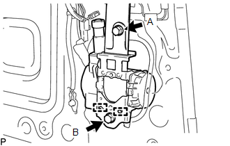
(c) Tighten bolt A, and then tighten bolt B.
Torque:
12.5 N·m {127 kgf·cm, 9 ft·lbf}
(for bolt A)
42 N·m {428 kgf·cm, 31 ft·lbf}
(for bolt B)
|
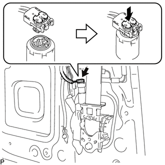
(d) Connect the pretensioner connector and lock the locking button as shown in the illustration. |
|
(e) Connect the shoulder anchor with the nut.
Torque:
42 N·m {428 kgf·cm, 31 ft·lbf}
(f) Check that the shoulder anchor rotates smoothly.
(g) Connect the floor anchor of the front seat outer belt assembly with the bolt.
(h) Check the ELR lock.
NOTICE:
The check should be performed with the front seat outer belt assembly installed.
(1) With the belt installed, check that the belt locks when it is pulled out quickly.
If the operation is not as specified, replace the front seat outer belt assembly.
(i) Remove the bolt to disconnect the floor anchor.
3. INSTALL ACCESS PANEL INSIDE HANDLE SUB-ASSEMBLY
Click here .gif)
4. INSTALL REAR DOOR TRIM BOARD SUB-ASSEMBLY
Click here
5. INSTALL DOOR PULL HANDLE
Click here
6. INSTALL ACCESS PANEL INSIDE HANDLE BEZEL
Click here
7. INSTALL LAP BELT OUTER ANCHOR COVER
Click here
8. INSTALL ACCESS PANEL REAR WEATHERSTRIP
Click here
9. CONNECT CABLE TO NEGATIVE BATTERY TERMINAL
Torque:
5.4 N·m {55 kgf·cm, 48 in·lbf}
NOTICE:
When disconnecting the cable, some systems need to be initialized after the cable is reconnected.
Click here
10. INSPECT SRS WARNING LIGHT
Click here
 Components
COMPONENTS
ILLUSTRATION
ILLUSTRATION
...
 Removal
REMOVAL
CAUTION / NOTICE / HINT
HINT:
Use the same procedure for both the RH and LH sides.
The procedure described below is for the LH side.
PROCEDURE
1. PRECAUTION
NOTICE:
Af ...
Other materials:
VSC Buzzer Circuit
DESCRIPTION
The skid control ECU (master cylinder solenoid) is connected to the combination
meter via CAN communication.
The combination meter has a built-in VSC warning buzzer:
Sounds intermittently to inform the driver if the temperature of hydraulic
brake booster has increased exc ...
Unable to Unlock Steering Wheel (Engine cannot Start)
DESCRIPTION
The steering lock actuator assembly activates the steering lock motor and moves
the lock bar into the steering column to lock the steering.
The steering may not unlock when the lock bar gets stuck in the lock hole of
the steering column. In this case, if the engine switch is turned ...
Pressure Control Solenoid "C" Electrical (Shift Solenoid Valve SL3) (P0798)
DESCRIPTION
Changing from 1st to 6th is performed by the ECM turning shift solenoid valves
SL1, SL2, SL3 and SL4 on and off. If an open or short circuit occurs in any of the
shift solenoid valves, the ECM controls the remaining normal shift solenoid valves
to allow the vehicle to be operated ...
