Toyota Tacoma (2015-2018) Service Manual: Inspection
INSPECTION
PROCEDURE
1. INSPECT TRANSMISSION FLOOR SHIFT ASSEMBLY (w/o Smart Key System)
HINT:
If the results of the following inspections are as specified but a malfunction has occurred, replace the transmission floor shift assembly.
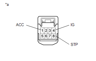
(a) Inspect the wire harness.
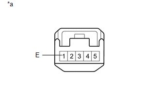
(1) Disconnect the shift lock control ECU connector.
|
(2) Measure the voltage according to the value(s) in the table below. Text in Illustration
Standard Voltage:
If the result is not as specified, repair or replace the wire harness or connector. |
|
|
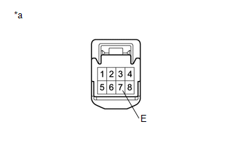
(3) Measure the resistance according to the value(s) in the table below. Text in Illustration
Standard Resistance:
If the result is not as specified, repair or replace the wire harness or connector. |
|
(b) Inspect the key interlock solenoid operation signal.
(1) Connect the shift lock control ECU connector.
|
(2) Measure the voltage according to the value(s) in the table below. Text in Illustration
Standard Voltage:
HINT: Do not disconnect the shift lock control ECU connector. If the result is not as specified, replace the transmission floor shift assembly. If the shift lock does not operate when the power source of the shift lock control ECU is normal and the resistance between the body ground and the shift lock control ECU is as specified, replace the transmission floor shift assembly. |
|
2. INSPECT TRANSMISSION FLOOR SHIFT ASSEMBLY (w/ Smart Key System)
HINT:
If the results of the following inspections are as specified but a malfunction has occurred, replace the transmission floor shift assembly.
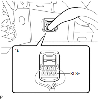
(a) Inspect the wire harness.
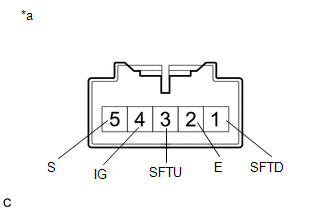
(1) Disconnect the shift lock control ECU connector.
|
(2) Measure the voltage according to the value(s) in the table below. Text in Illustration
Standard Voltage:
If the result is not as specified, repair or replace the wire harness or connector. |
|
|
(3) Measure the resistance according to the value(s) in the table below. Text in Illustration
Standard Resistance:
If the result is not as specified, repair or replace the wire harness or connector. If the shift lock does not operate when the power source of the shift lock control ECU is normal and the resistance between the body ground and the shift lock control ECU is as specified, replace the transmission floor shift assembly. |
|
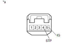
3. INSPECT TRANSMISSION CONTROL SWITCH (TRANSMISSION FLOOR SHIFT ASSEMBLY)
(a) Disconnect the transmission control switch connector.
|
(b) Measure the resistance according to the value(s) in the table below. Text in Illustration
Standard Resistance:
If the result is not as specified, replace the transmission floor shift assembly. |
|
 Removal
REMOVAL
PROCEDURE
1. REMOVE FRONT CONSOLE BOX
(See page )
2. DISCONNECT TRANSMISSION CONTROL CABLE ASSEMBLY
(a) Move the shift lever to N.
(b) Disconnect the end of the transmission control ca ...
 Installation
INSTALLATION
PROCEDURE
1. INSTALL TRANSMISSION FLOOR SHIFT ASSEMBLY
(a) Install the transmission floor shift assembly to the vehicle body with the
4 bolts.
Torque:
14 N·m {143 kgf·cm, 10 ft ...
Other materials:
AUTO LSD Indicator Light Remains ON
DESCRIPTION
During normal mode, pressing the VSC OFF switch for a short amount of time changes
vehicle to AUTO LSD mode.
WIRING DIAGRAM
CAUTION / NOTICE / HINT
NOTICE:
When replacing the brake actuator assembly, perform calibration (See page
).
PROCEDURE
1.
CHECK ...
Installation
INSTALLATION
PROCEDURE
1. INSTALL FRONT DIFFERENTIAL CARRIER ASSEMBLY
(a) Connect the actuator hose and connector.
(b) Install the No. 1 mounting support with the 3 bolts.
Torque:
186 N·m {1899 kgf·cm, 138 ft·lbf}
(c) Install the No. 2 mounting support with the 2 bolts.
Torque:
160 N ...
Vehicle Speed Sensor Circuit (C1AA3)
DESCRIPTION
The forward recognition camera receives vehicle speed signals from the skid control
ECU. If the skid control ECU receives a vehicle speed sensor malfunction signal,
it informs the forward recognition camera via CAN communication, and DTC C1AA3 is
stored.
DTC No.
...
