Toyota Tacoma (2015-2018) Service Manual: GPS Mark is not Displayed
PROCEDURE
|
1. |
CHECK CABIN |
(a) Check the cabin for any object that might interrupt radio reception or additional devices which use radio waves on the instrument panel. If such an object exists, remove it and check if the GPS mark reappears.
HINT:
The GPS uses extremely weak radio waves originating from satellites. If the signal is interrupted by obstructions or other radio waves, the GPS may not be able to properly receive the signal.
OK:
The GPS mark appears.
| OK | .gif) |
NORMAL OPERATION |
|
.gif)
|
2. |
CHECK SURROUNDINGS |
(a) Check if the vehicle is in a location where GPS signal reception is poor. If the vehicle is in such a place, relocate the vehicle and check if the GPS mark reappears.
HINT:
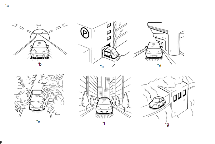
The GPS uses 24 satellites in 6 orbits. At any point in time, 4 satellites should be able to pinpoint your vehicle. However, GPS signals may not reach the vehicle due to influence from the surroundings, vehicle direction and time. For examples, see the following illustration.
OK:
The GPS mark is displayed.
Text in Illustration|
*a |
Example |
*b |
In a tunnel |
|
*c |
In a building |
*d |
Under an overpass |
|
*e |
On a forest or tree-lined path |
*f |
Between tall buildings |
|
*g |
Under a cliff or overhang |
- |
- |
| OK | |
SYSTEM RETURNS TO NORMAL |
|
|
3. |
CHECK GPS INFORMATION (OPERATION CHECK) |
.png)
(a) Enter the "System Sensor Check" screen. Refer to Check GPS & Vehicle Sensors
in Operation Check (See page .gif) ).
).
(b) Check how many of the following codes appear in the "Reception number" column.
HINT:
T or P appears.
OK:
At least 3 codes appear.
| OK | |
REPLACE NAVIGATION RECEIVER ASSEMBLY |
| NG | |
PROCEED TO NEXT SUSPECTED AREA SHOWN IN PROBLEM SYMPTOMS TABLE |
 Cursor or Map Rotates when Vehicle Stopped
PROCEDURE
1.
CHECK CONDITION
(a) Check with the customer if the vehicle has been turned by a turntable.
OK:
Vehicle has not been turned by a turntab ...
 Voice Guidance does not Function
PROCEDURE
1.
CHECK VOICE GUIDANCE SETTING
(a) Check that the voice guidance settings are not off.
OK:
Voice guidance settings are not off.
NG
C ...
Other materials:
Adjustment
ADJUSTMENT
PROCEDURE
1. PREPARE VEHICLE FOR HEADLIGHT AIM ADJUSTMENT
(a) Prepare the vehicle:
Ensure that there is no damage or deformation to the body around the
headlights.
Fill the fuel tank.
Make sure that the oil is filled to the specified level.
Make sure that the co ...
Data List / Active Test
DATA LIST / ACTIVE TEST
1. DATA LIST
HINT:
Using the Techstream to read the Data List allows the values or states of switches,
sensors, actuators and other items to be read without removing any parts. This non-intrusive
inspection can be very useful because intermittent conditions or signals ...
Touch Panel Switch does not Function
PROCEDURE
1.
CHECK MULTI-DISPLAY
(a) Check if there is any foreign matter caught between the display and exterior
frame of the multi-display.
OK:
No foreign matter is caught between the display and exterior frame of the multi-display.
HINT:
If there is foreig ...
