Toyota Tacoma (2015-2018) Service Manual: System Diagram
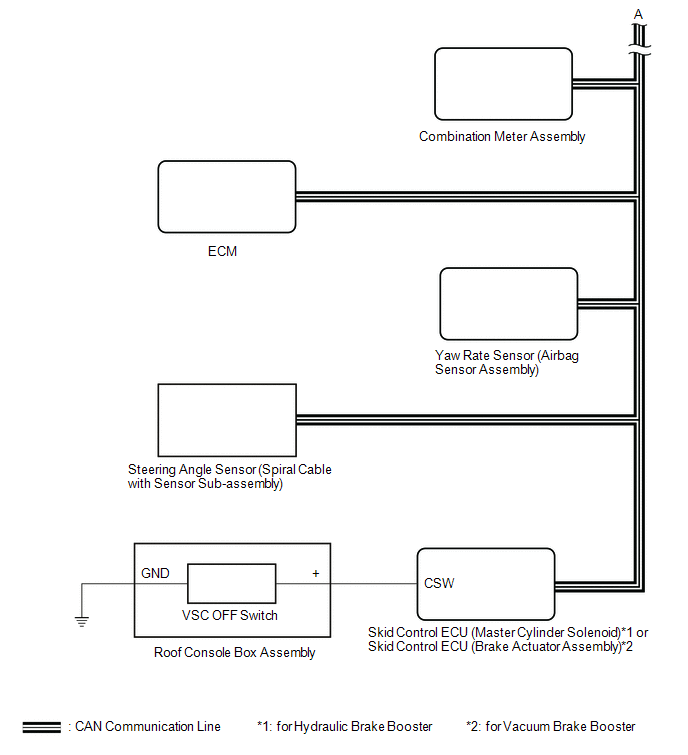
SYSTEM DIAGRAM
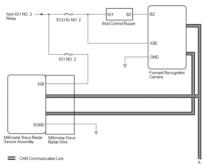
 Communication Table
|
Sender |
Receiver |
Signal |
Line |
|---|---|---|---|
|
Millimeter Wave Radar Sensor Assembly |
Forward Recognition Camera |
|
CAN |
|
Skid Control ECU (Master Cylinder Solenoid)*1 or Skid Control ECU (Brake Actuator Assembly)*2 |
|
||
|
ECM |
|
||
|
Combination Meter Assembly |
|
||
|
Forward Recognition Camera |
Millimeter Wave Radar Sensor Assembly |
|
|
|
Skid Control ECU (Master Cylinder Solenoid)*1 or Skid Control ECU (Brake Actuator Assembly)*2 |
Millimeter Wave Radar Sensor Assembly |
|
|
|
Forward Recognition Camera |
|
||
|
Combination Meter Assembly |
|
||
|
Yaw Rate Sensor (Airbag Sensor Assembly) |
Millimeter Wave Radar Sensor Assembly |
|
|
|
Forward Recognition Camera |
|||
|
Main Body ECU (Multiplex Network Body ECU) |
Millimeter Wave Radar Sensor Assembly |
|
|
|
Forward Recognition Camera |
|||
|
Steering Angle Sensor (Spiral Cable with Sensor Sub-assembly) |
Millimeter Wave Radar Sensor Assembly |
|
|
|
Forward Recognition Camera |
|||
|
ECM |
Millimeter Wave Radar Sensor Assembly |
|
- *1: for Hydraulic Brake Booster
- *2: for Vacuum Brake Booster
 System Description
SYSTEM DESCRIPTION
PRE-COLLISION SYSTEM DESCRIPTION
(a) The pre-collision system uses the pre-collision warning control, pre-collision
brake assist control and pre-collision braking control to hel ...
 Customize Parameters
CUSTOMIZE PARAMETERS
NOTICE:
When the customer requests a change in a function, first make sure that
the function can be customized.
Make a note of the current settings before custom ...
Other materials:
Fender Panel Mudguard
Components
COMPONENTS
ILLUSTRATION
ILLUSTRATION
Installation
INSTALLATION
CAUTION / NOTICE / HINT
HINT:
Use the same procedure for the RH side and LH side.
The following procedure is for the LH side.
PROCEDURE
1. INSTALL FRONT FENDER MUDGUARD
(a) Install the fron ...
Data List / Active Test
DATA LIST / ACTIVE TEST
NOTICE:
In the table below, the values listed under "Normal Condition" are reference
values. Do not depend solely on these reference values when deciding whether a part
is faulty or not.
HINT:
Using the Techstream to read the Data List allows the values or s ...
Camera Heater
Components
COMPONENTS
ILLUSTRATION
*1
FORWARD RECOGNITION WITH HEATER HOOD SUB-ASSEMBLY
-
-
Removal
REMOVAL
PROCEDURE
1. REMOVE FORWARD RECOGNITION CAMERA
Click here
2. REMOVE FORWARD RECOGNITION WITH HEATER HOOD SUB-ASSEMBLY
NOT ...
