Toyota Tacoma (2015-2018) Service Manual: Removal
REMOVAL
CAUTION / NOTICE / HINT
HINT:
- Use the same procedure for the LH side and RH side.
- The following procedure listed is for the LH side.
PROCEDURE
1. REMOVE FRONT WHEEL
2. DRAIN BRAKE FLUID
NOTICE:
Immediately wash off any brake fluid that comes into contact with any painted surfaces.
3. REMOVE FRONT DISC BRAKE ANTI-RATTLE WITH HOLE PIN
|
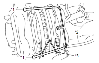
(a) for Pin Hold Clip Type A: (1) Remove the pin hold clip from the 2 front disc brake anti-rattle with hole pins. Text in Illustration
NOTICE: The pin hold clip can be used again if it has sufficient rebound; no deformation or wear; and has had all rust, dirt and foreign matter cleaned off. (2) Remove the 2 front disc brake anti-rattle with hole pins from the disc brake cylinder assembly. (3) Remove the anti-rattle spring from the front disc brake pad. NOTICE: The anti-rattle spring can be used again if it has sufficient rebound; no deformation, cracks or wear; and has had all rust, dirt and foreign matter cleaned off. |
|
|
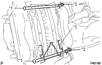
(b) for Pin Hold Clip Type B: (1) Remove the 2 pin hold clips from the 2 front disc brake anti-rattle with hole pins. Text in Illustration
(2) Remove the 2 front disc brake anti-rattle with hole pins from the disc brake cylinder assembly. (3) Remove the anti-rattle spring from the front disc brake pad. NOTICE: The anti-rattle spring can be used again if it has sufficient rebound; no deformation, cracks or wear; and has had all rust, dirt and foreign matter cleaned off. |
|
4. REMOVE FRONT DISC BRAKE PAD KIT
(a) Remove the 2 front disc brake pads with front anti squeal shim from the disc brake cylinder assembly.
5. REMOVE FRONT ANTI SQUEAL SHIM KIT
(a) Remove the 2 front anti squeal shims from each of the front disc brake pads.
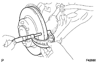
6. REMOVE DISC BRAKE CYLINDER ASSEMBLY
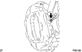
(a) Using a union nut wrench 10 mm, separate the brake tube from the disc brake cylinder assembly.
HINT:
Use a container to collect the brake fluid as it drains out.
|
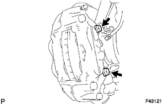
(b) Remove the 2 bolts and the disc brake cylinder assembly. |
|
7. INSPECT DISC THICKNESS
(a) Using a micrometer, measure the disc thickness.
Standard thickness:
28.0 mm (1.10 in.)
Minimum thickness:
26.0 mm (1.03 in.)
If the disc thickness is less than the minimum, replace the front disc.
8. REMOVE FRONT DISC
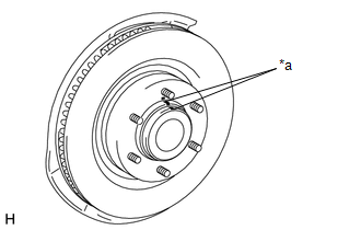
(a) Place matchmarks on the front disc and the front axle hub and remove the front disc.
Text in Illustration|
*a |
Matchmark |
 Disassembly
DISASSEMBLY
PROCEDURE
1. REMOVE CYLINDER BOOT
(a) Using a screwdriver, remove the 4 cylinder boots from the caliper.
2. REMOVE FRONT DISC BRAKE PISTON
(a) Prepare a wooden plate to hold the p ...
 Inspection
INSPECTION
PROCEDURE
1. INSPECT BRAKE CYLINDER AND PISTON
(a) Check the cylinder bore and piston for rust and scoring.
2. INSPECT PAD LINING THICKNESS
(a) Using a ruler, measure the pad lining ...
Other materials:
Rear Differential Lock Position SW Stuck ON (P17BC)
DESCRIPTION
This DTC is output when an ON malfunction of the differential lock indicator
switch is detected.
DTC No.
Detection Item
DTC Detection Condition
Trouble Area
P17BC
Rear Differential Lock Position SW Stuck ON
...
Ambient Temperature Sensor
Components
COMPONENTS
ILLUSTRATION
Inspection
INSPECTION
PROCEDURE
1. INSPECT AMBIENT TEMPERATURE SENSOR
(a) Measure the resistance according to the value(s) in the table below.
Standard resistance:
Tester Connection
Condition
...
Utility
UTILITY
NOTICE:
If the forward recognition camera has been replaced with a new one or
the windshield glass has been removed and installed, it is necessary to
perform Forward Recognition Camera Axis Adjustment. If the system is turned
on without performing Forward Recognition Ca ...
