Toyota Tacoma (2015-2018) Service Manual: Air Mix Damper Position Sensor Circuit (Passenger Side) (B1431/31)
DESCRIPTION
This sensor detects the position of the air mix damper (for front passenger side) and sends the appropriate signals to the air conditioning amplifier assembly. The position sensor is built into the No. 2 air conditioning radiator damper servo sub-assembly (for front passenger side air mix).
|
DTC No. |
DTC Detection Condition |
Trouble Area |
|---|---|---|
|
B1431/31 |
Short to ground or power source circuit air mix damper position sensor (for front passenger side) circuit. |
|
WIRING DIAGRAM
PROCEDURE
|
1. |
READ VALUE USING TECHSTREAM |
(a) Connect the Techstream to the DLC3.
(b) Turn the ignition switch to ON.
(c) Turn the Techstream on.
(d) Operate the front passenger side temperature switch.
(e) Enter the following menus: Body Electrical / Air Conditioner / Data List.
(f) Check the value(s) by referring to the table below.
Air Conditioner|
Tester Display |
Measurement Item/Range |
Normal Condition |
Diagnostic Note |
|---|---|---|---|
|
Air Mix Damper Position (Passenger Side) |
Air mix damper servo motor (for front passenger side) actual position / Min.: -14.0% Max.: 113.5% |
MAX COOL: 0.0% MAX HOT: 100.0% |
- |
|
Air Mix Damper Target (Passenger Side) |
Air mix damper servo motor (for front passenger side) target position / Min.: -14.0% Max.: 113.5% |
MAX COOL: 0.0% MAX HOT: 100.0% |
- |
OK:
The display is as specified in the Normal Condition column.
|
Result |
Proceed to |
|---|---|
|
NG |
A |
|
OK (When troubleshooting according to Problem Symptoms Table) |
B |
|
OK (When troubleshooting according to the DTC) |
C |
| B | .gif) |
PROCEED TO NEXT SUSPECTED AREA SHOWN IN PROBLEM SYMPTOMS TABLE |
| C | |
REPLACE AIR CONDITIONING AMPLIFIER ASSEMBLY |
|
.gif)
|
2. |
INSPECT NO. 2 AIR CONDITIONING RADIATOR DAMPER SERVO SUB-ASSEMBLY (FOR FRONT PASSENGER SIDE AIR MIX) |
(a) Remove the No. 2 air conditioning radiator damper servo sub-assembly (for
front passenger side air mix) (See page .gif) ).
).
(b) Inspect the No. 2 air conditioning radiator damper servo sub-assembly (for
front passenger side air mix) (See page ).
| NG | |
REPLACE NO. 2 AIR CONDITIONING RADIATOR DAMPER SERVO SUB-ASSEMBLY (FOR FRONT PASSENGER SIDE AIR MIX) |
|
|
3. |
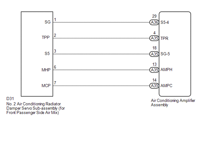
CHECK HARNESS AND CONNECTOR (NO. 2 AIR CONDITIONING RADIATOR DAMPER SERVO SUB-ASSEMBLY - AIR CONDITIONING AMPLIFIER ASSEMBLY) |
(a) Disconnect the D31 No. 2 air conditioning radiator damper servo sub-assembly (for front passenger side air mix) connector.
(b) Disconnect the A35 and A36 air conditioning amplifier assembly connectors.
(c) Measure the resistance according to the value(s) in the table below.
Standard Resistance:
|
Tester Connection |
Condition |
Specified Condition |
|---|---|---|
|
D31-1 (SG) - A36-29 (S5-4) |
Always |
Below 1 Ω |
|
D31-2 (TPP) - A35-4 (TPR) |
Always |
Below 1 Ω |
|
D31-3 (S5) - A35-18 (SG-5) |
Always |
Below 1 Ω |
|
D31-1 (SG) or A36-29 (S5-4) - Body ground |
Always |
10 kΩ or higher |
|
D31-2 (TPP) or A35-4 (TPR) - Body ground |
Always |
10 kΩ or higher |
|
D31-3 (S5) or A35-18 (SG-5) - Body ground |
Always |
10 kΩ or higher |
| OK | |
REPLACE AIR CONDITIONING AMPLIFIER ASSEMBLY |
| NG | |
REPAIR OR REPLACE HARNESS OR CONNECTOR |
 Air Mix Damper Control Servo Motor Circuit (Driver Side) (B1446/46)
DESCRIPTION
This No. 3 air conditioning radiator damper servo sub-assembly (for driver side
air mix) is controlled by the air conditioning amplifier assembly and moves the
air mix damper (for dri ...
 Air Inlet Damper Position Sensor Circuit (B1432/32)
DESCRIPTION
This sensor detects the position of the air inlet damper and sends the appropriate
signals to the air conditioning amplifier assembly. The position sensor is built
into the No. 1 air ...
Other materials:
Air Inlet Damper Control Servo Motor Circuit (B1442/42)
DESCRIPTION
This No. 1 air conditioning servo assembly (fresh/recirculation damper) is controlled
by the air conditioning amplifier assembly and moves the air inlet damper to the
desired position.
DTC No.
DTC Detection Condition
Trouble Area
B1 ...
Installation
INSTALLATION
PROCEDURE
1. INSTALL SPIRAL CABLE SUB-ASSEMBLY WITH SENSOR
(a) Check that the ignition switch is off.
(b) Check that the battery negative (-) terminal is disconnected.
CAUTION:
Wait at least 90 seconds after disconnecting the ca ...
Rear Combination Light Assembly
Components
COMPONENTS
ILLUSTRATION
Disassembly
DISASSEMBLY
CAUTION / NOTICE / HINT
HINT:
Use the same procedure for both the LH and RH sides.
The procedure described below is for the LH side.
PROCEDURE
1. REMOVE TAIL AND TURN SIGNAL LIGHT BULB
(a) Turn th ...
