Toyota Tacoma (2015-2018) Service Manual: Air Mix Damper Control Servo Motor Circuit (Driver Side) (B1446/46)
DESCRIPTION
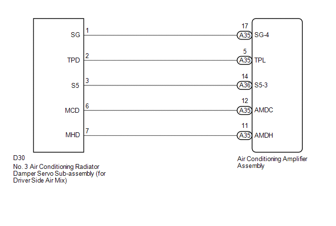
This No. 3 air conditioning radiator damper servo sub-assembly (for driver side air mix) is controlled by the air conditioning amplifier assembly and moves the air mix damper (for driver side) to the desired position.
|
DTC No. |
DTC Detection Condition |
Trouble Area |
|---|---|---|
|
B1446/46 |
Air mix damper position sensor (for driver side) value does not change even if air conditioning amplifier assembly operates air mix damper servo motor (for driver side) |
|
WIRING DIAGRAM
PROCEDURE
|
1. |
READ VALUE USING TECHSTREAM |
(a) Connect the Techstream to the DLC3.
(b) Turn the ignition switch to ON.
(c) Turn the Techstream on.
(d) Operate the driver side temperature switch.
(e) Enter the following menus: Body Electrical / Air Conditioner / Data List.
(f) Check the value(s) by referring to the table below.
Air Conditioner|
Tester Display |
Measurement Item/Range |
Normal Condition |
Diagnostic Note |
|---|---|---|---|
|
Air Mix Damper Position (Driver Side) |
Air mix damper servo motor (for driver side) actual position / Min.: -14.0% Max.: 113.5% |
MAX COOL: 0.0% MAX HOT: 100.0% |
- |
|
Air Mix Damper Target (Driver Side) |
Air mix damper servo motor (for driver side) target position / Min.: -14.0% Max.: 113.5% |
MAX COOL: 0.0% MAX HOT: 100.0% |
- |
OK:
The display is as specified in the Normal Condition column.
|
Result |
Proceed to |
|---|---|
|
NG |
A |
|
OK (When troubleshooting according to Problem Symptoms Table) |
B |
|
OK (When troubleshooting according to the DTC) |
C |
| B | .gif) |
PROCEED TO NEXT SUSPECTED AREA SHOWN IN PROBLEM SYMPTOMS TABLE |
| C | |
REPLACE AIR CONDITIONING AMPLIFIER ASSEMBLY |
|
.gif)
|
2. |
INSPECT NO. 3 AIR CONDITIONING RADIATOR DAMPER SERVO SUB-ASSEMBLY (FOR DRIVER SIDE AIR MIX) |
(a) Remove the No. 3 air conditioning radiator damper servo sub-assembly (for
driver side air mix) (See page .gif) ).
).
(b) Inspect the No. 3 air conditioning radiator damper servo sub-assembly (for
driver side air mix) (See page ).
| NG | |
REPLACE NO. 3 AIR CONDITIONING RADIATOR DAMPER SERVO SUB-ASSEMBLY (FOR DRIVER SIDE AIR MIX) |
|
|
3. |
CHECK HARNESS AND CONNECTOR (NO. 3 AIR CONDITIONING RADIATOR DAMPER SERVO SUB-ASSEMBLY - AIR CONDITIONING AMPLIFIER ASSEMBLY) |
(a) Disconnect the D30 No. 3 air conditioning radiator damper servo sub-assembly (for driver side air mix) connector.
(b) Disconnect the A35 air conditioning amplifier assembly connector.
(c) Measure the resistance according to the value(s) in the table below.
Standard Resistance:
|
Tester Connection |
Condition |
Specified Condition |
|---|---|---|
|
D30-6 (MCD) - A35-12 (AMDC) |
Always |
Below 1 Ω |
|
D30-7 (MHD) - A35-11 (AMDH) |
Always |
Below 1 Ω |
|
D30-6 (MCD) or A35-12 (AMDC) - Body ground |
Always |
10 kΩ or higher |
|
D30-7 (MHD) or A35-11 (AMDH) - Body ground |
Always |
10 kΩ or higher |
| OK | |
REPLACE AIR CONDITIONING AMPLIFIER ASSEMBLY |
| NG | |
REPAIR OR REPLACE HARNESS OR CONNECTOR |
 Lost Communication with Front Panel LIN (B14B2)
DESCRIPTION
The air conditioning control assembly communicates with the air conditioning
amplifier assembly through the LIN communication system.
If the LIN communication system malfunctions, the ...
 Air Mix Damper Position Sensor Circuit (Passenger Side) (B1431/31)
DESCRIPTION
This sensor detects the position of the air mix damper (for front passenger side)
and sends the appropriate signals to the air conditioning amplifier assembly. The
position sensor is ...
Other materials:
Clutch Switch
Components
COMPONENTS
ILLUSTRATION
Removal
REMOVAL
PROCEDURE
1. PRECAUTION
NOTICE:
After turning the engine switch off, waiting time may be required before disconnecting
the cable from the battery terminal. Therefore, make sure to read the disconnecting
the cable from the battery t ...
Customize Parameters
CUSTOMIZE PARAMETERS
PROCEDURE
1. CUSTOMIZE AIR CONDITIONING SYSTEM
(a) Customizing with the Techstream
NOTICE:
When the customer requests a change in a function, first make sure that
the function can be customized.
Be sure to make a note of the current settings before customizi ...
ECU Power Source Circuit
DESCRIPTION
This circuit supplies power to the millimeter wave radar sensor assembly when
the ignition switch is ON.
WIRING DIAGRAM
CAUTION / NOTICE / HINT
NOTICE:
Inspect the fuses for circuits related to this system before performing the following
inspection procedure.
PROCEDURE
...
