Toyota Tacoma (2015-2018) Service Manual: Installation
INSTALLATION
PROCEDURE
1. INSTALL SPIRAL CABLE SUB-ASSEMBLY WITH SENSOR
|
(a) Check that the ignition switch is off. |
|
(b) Check that the battery negative (-) terminal is disconnected.
CAUTION:
Wait at least 90 seconds after disconnecting the cable from the negative (-) battery terminal to prevent airbag and seat belt pretensioner activation.
(c) Confirm that the front tires face straight forward.
(d) Engage the 3 claws and install the spiral cable sub-assembly with sensor.
NOTICE:
When replacing the spiral cable sub-assembly with sensor with a new one, remove the lock pin before installing the steering wheel.
(e) Connect the connectors to the spiral cable sub-assembly with sensor.
NOTICE:
When handling the airbag connector, take care not to damage the airbag wire harness.
2. REMOVE UPPER STEERING COLUMN COVER
.gif)
3. INSTALL LOWER STEERING COLUMN COVER
4. ADJUST SPIRAL CABLE
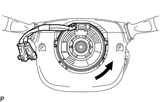
(a) Rotate the spiral cable sub-assembly with sensor counterclockwise slowly by hand until it feels firm.
NOTICE:
Do not turn the spiral cable sub-assembly with sensor by the airbag wire harness.
|
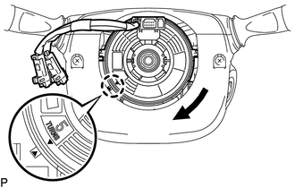
(b) Rotate the spiral cable sub-assembly with sensor clockwise approximately 2.5 turns to align the marks. NOTICE: Do not turn the spiral cable sub-assembly with sensor by the airbag wire harness. HINT: The spiral cable sub-assembly withy sensor will rotate approximately 2.5 turns to both the left and right from the center. |
|
5. INSTALL STEERING WHEEL ASSEMBLY
6. INSTALL STEERING PAD
(See page )
7. INSPECT STEERING PAD
8. INSPECT SRS WARNING LIGHT
(See page )
 Components
COMPONENTS
ILLUSTRATION
...
 Removal
REMOVAL
PROCEDURE
1. REMOVE STEERING PAD
(See page )
2. REMOVE STEERING WHEEL ASSEMBLY
3. REMOVE LOWER STEERING COLUMN COVER
4. REMOVE UPPER STEERING COLUMN COVER
5. REMOVE SPIRAL ...
Other materials:
Reassembly
REASSEMBLY
PROCEDURE
1. INSPECT CENTER NO. 2 SUPPORT BEARING ASSEMBLY
(a) Turn the center bearing by hand, check that it turns smoothly without catching
and that there are no cracks or damage.
If there are any defects, replace it.
2. INSTALL CENTER NO. 2 SUPPORT BEARING ASSEMBLY
(a) Instal ...
Data Signal Circuit between Stereo Jack Adapter and Extension Module
DESCRIPTION
The No. 1 stereo jack adapter assembly sends the sound data signal or image data
signal from a USB device to the navigation receiver assembly via this circuit.
WIRING DIAGRAM
PROCEDURE
1.
CHECK HARNESS AND CONNECTOR (NAVIGATION RECEIVER ASSEMBLY - NO. 1 STE ...
Installation
INSTALLATION
CAUTION / NOTICE / HINT
HINT:
Use the same procedure for the RH side and LH side.
The following procedure is for the LH side.
When installing a new front fender wheel opening moulding or quarter
panel wheel opening moulding, heat the vehicle body and front fender ...
