Toyota Tacoma (2015-2018) Service Manual: Air Inlet Damper Control Servo Motor Circuit (B1442/42)
DESCRIPTION
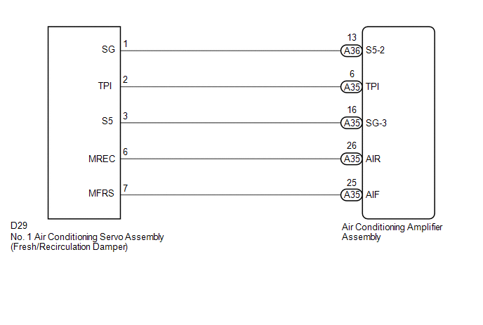
This No. 1 air conditioning servo assembly (fresh/recirculation damper) is controlled by the air conditioning amplifier assembly and moves the air inlet damper to the desired position.
|
DTC No. |
DTC Detection Condition |
Trouble Area |
|---|---|---|
|
B1442/42 |
Air inlet damper position sensor value does not change even if air conditioning amplifier assembly operates air inlet damper servo motor. |
|
WIRING DIAGRAM
PROCEDURE
|
1. |
READ VALUE USING TECHSTREAM |
(a) Connect the Techstream to the DLC3.
(b) Turn the ignition switch to ON.
(c) Turn the Techstream on.
(d) Operate the recirculation/fresh switch.
(e) Enter the following menus: Body Electrical / Air Conditioner / Data List.
(f) Check the value(s) by referring to the table below.
Air Conditioner|
Tester Display |
Measurement Item/Range |
Normal Condition |
Diagnostic Note |
|---|---|---|---|
|
Air Inlet Damper Position |
Air inlet damper servo motor actual position / Air inlet damper servo motor actual position / Min.: -14.0% Max.: 113.5% |
FRESH: 0.0% RECIRCULATION: 100.0% |
- |
|
Air Inlet Damper Target |
Air inlet damper servo motor target position / Min.: -14.0% Max.: 113.5% |
FRESH: 0.0% RECIRCULATION: 100.0% |
- |
OK:
The display is as specified in the Normal Condition column.
|
Result |
Proceed to |
|---|---|
|
NG |
A |
|
OK (When troubleshooting according to Problem Symptoms Table) |
B |
|
OK (When troubleshooting according to the DTC) |
C |
| B | .gif) |
PROCEED TO NEXT SUSPECTED AREA SHOWN IN PROBLEM SYMPTOMS TABLE |
| C | |
REPLACE AIR CONDITIONING AMPLIFIER ASSEMBLY |
|
.gif)
|
2. |
INSPECT NO. 1 AIR CONDITIONING SERVO ASSEMBLY (FRESH/RECIRCULATION DAMPER) |
(a) Remove the No. 1 air conditioning servo assembly (fresh/recirculation damper)
(See page .gif) ).
).
(b) Inspect the No. 1 air conditioning servo assembly (fresh/recirculation damper)
(See page ).
| NG | |
REPLACE NO. 1 AIR CONDITIONING SERVO ASSEMBLY (FRESH/RECIRCULATION DAMPER) |
|
|
3. |
CHECK HARNESS AND CONNECTOR (NO. 1 AIR CONDITIONING SERVO ASSEMBLY - AIR CONDITIONING AMPLIFIER ASSEMBLY) |
(a) Disconnect the D29 No. 1 air conditioning servo assembly (fresh/recirculation damper).
(b) Disconnect the A35 air conditioning amplifier assembly connector.
(c) Measure the resistance according to the value(s) in the table below.
Standard Resistance:
|
Tester Connection |
Condition |
Specified Condition |
|---|---|---|
|
D29-6 (MREC) - A35-26 (AIR) |
Always |
Below 1 Ω |
|
D29-7 (MFRS) - A35-25 (AIF) |
Always |
Below 1 Ω |
|
D29-6 (MREC) or A35-26 (AIR) - Body ground |
Always |
10 kΩ or higher |
|
D29-7 (MFRS) or A35-25 (AIF) - Body ground |
Always |
10 kΩ or higher |
| OK | |
REPLACE AIR CONDITIONING AMPLIFIER ASSEMBLY |
| NG | |
REPAIR OR REPLACE HARNESS OR CONNECTOR |
 Air Mix Damper Position Sensor Circuit (Driver Side) (B1436/36)
DESCRIPTION
This sensor detects the position of the air mix damper (for driver side) and
sends the appropriate signals to the air conditioning amplifier assembly. The position
sensor is built int ...
 Room Temperature Sensor Circuit (B1411/11)
DESCRIPTION
The cooler thermistor (room temperature sensor) is installed in the instrument
panel to detect the cabin temperature which is used to control the air conditioning
system AUTO mode. Th ...
Other materials:
Problem Symptoms Table
PROBLEM SYMPTOMS TABLE
HINT:
Use the table below to help determine the cause of problem symptoms.
If multiple suspected areas are listed, the potential causes of the symptoms
are listed in order of probability in the "Suspected Area" column of the
table. Check each sy ...
Removal
REMOVAL
CAUTION / NOTICE / HINT
HINT:
Use the same procedure for the RH and LH sides.
The procedure listed below is for the LH side.
PROCEDURE
1. REMOVE REAR DOOR FRAME GARNISH
(See page )
2. REMOVE REAR DOOR INSIDE HANDLE BEZEL PLUG
(See page )
3. REMOVE REAR ARMREST ...
System Diagram
SYSTEM DIAGRAM
Circuit Description
Component
Outline
Steering Lock ECU (Steering Lock Actuator or UPR Bracket Assembly)
The steering is locked and unlocked by communicating with the
certification ECU (smart key ECU assembly) via L ...
