Toyota Tacoma (2015-2018) Service Manual: Rear Combination Light Assembly
Components
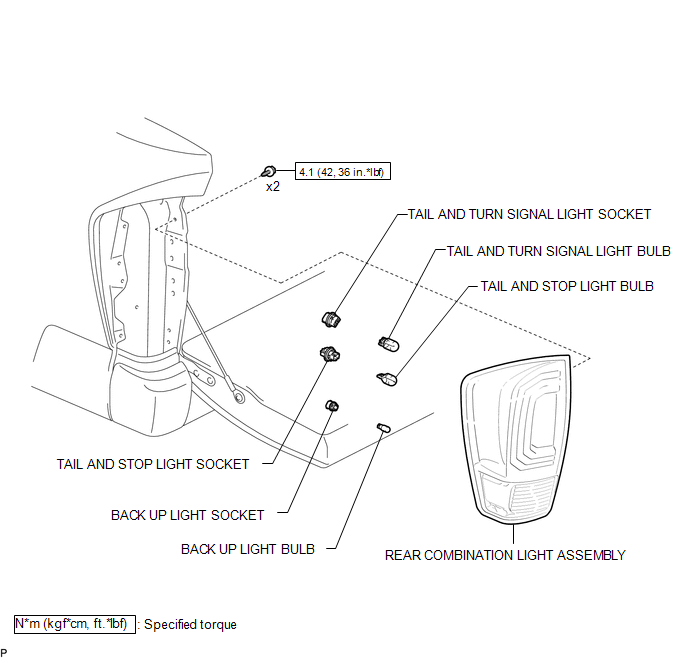
COMPONENTS
ILLUSTRATION
Disassembly
DISASSEMBLY
CAUTION / NOTICE / HINT
HINT:
- Use the same procedure for both the LH and RH sides.
- The procedure described below is for the LH side.
PROCEDURE
1. REMOVE TAIL AND TURN SIGNAL LIGHT BULB
|
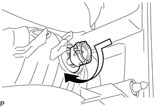
(a) Turn the tail and turn signal light socket with the tail and turn signal light bulb in the direction indicated by the arrow shown in the illustration to remove them. |
|
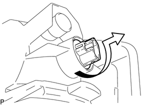
(b) Remove the tail and turn signal light bulb from the tail and turn signal light socket.
2. REMOVE TAIL AND STOP LIGHT BULB
|
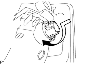
(a) Turn the tail and stop light socket with the tail and stop light bulb in the direction indicated by the arrow shown in the illustration to remove them. |
|
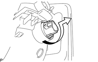
(b) Remove the tail and stop light bulb from the tail and stop light socket.
3. REMOVE BACK UP LIGHT BULB
|
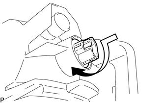
(a) Turn the back up light socket with the back up light bulb in the direction indicated by the arrow shown in the illustration to remove them. |
|
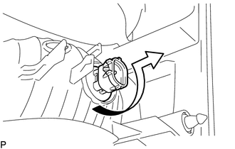
(b) Remove the back up light bulb from the back up light socket.
Reassembly
REASSEMBLY
CAUTION / NOTICE / HINT
HINT:
- Use the same procedure for both the LH and RH sides.
- The procedure described below is for the LH side.
PROCEDURE
1. INSTALL BACK UP LIGHT BULB
(a) Install the back up light bulb to the back up light socket.
|
(b) Turn the back up light socket with back up light bulb in the direction indicated by the arrow shown in the illustration to install them. |
|
2. INSTALL TAIL AND STOP LIGHT BULB
(a) Install the tail and stop light bulb to the tail and stop light socket.
|
(b) Turn the tail and stop light socket with tail and stop light bulb in the direction indicated by the arrow shown in the illustration to install them. |
|
3. INSTALL TAIL AND TURN SIGNAL LIGHT BULB
(a) Install the tail and turn signal light bulb to the tail and turn signal light socket.
|
(b) Turn the tail and turn signal light socket with tail and turn signal light bulb in the direction indicated by the arrow shown in the illustration to install them. |
|
Removal
REMOVAL
CAUTION / NOTICE / HINT
HINT:
- Use the same procedure for both the LH and RH sides.
- The procedure described below is for the LH side.
PROCEDURE
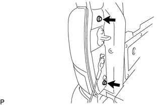
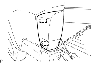
1. REMOVE REAR COMBINATION LIGHT ASSEMBLY
|
(a) Remove the 2 bolts. |
|
|
(b) Disengage the 2 pins to separate the rear combination light assembly. |
|
|
(c) Disengage the 2 guides to separate the wire harness. |
|
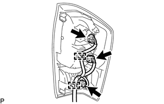
(d) Disconnect the 3 connectors to remove the rear combination light assembly.
Installation
INSTALLATION
CAUTION / NOTICE / HINT
HINT:
- Use the same procedure for both the LH and RH sides.
- The procedure described below is for the LH side.
PROCEDURE
1. INSTALL REAR COMBINATION LIGHT ASSEMBLY
(a) Connect the 3 connectors.
(b) Engage the 2 guides to install the wire harness.
(c) Engage the 2 pins to install the rear combination light assembly.
(d) Install the 2 bolts.
Torque:
4.1 N·m {42 kgf·cm, 36 in·lbf}
 Personal Light Assembly
Components
COMPONENTS
ILLUSTRATION
Installation
INSTALLATION
PROCEDURE
1. INSTALL MAP LIGHT BULB
(a) Install the 2 map light bulbs to the 2 map light sockets.
(b) Turn the 2 m ...
 Rear Door Courtesy Switch
Inspection
INSPECTION
PROCEDURE
1. INSPECT REAR DOOR COURTESY SWITCH
(a) Check the resistance.
(1) Measure the resistance using an ohmmeter, and check the results in accordance
with the value ...
Other materials:
Installation
INSTALLATION
CAUTION / NOTICE / HINT
HINT:
The following procedures are for BD22 (w/o Differential Lock).
PROCEDURE
1. INSTALL DIFFERENTIAL CARRIER ASSEMBLY REAR
(a) Clean the contact surfaces of the rear differential carrier assembly and
axle housing.
(b) Install the rear differential carr ...
Television Camera
Components
COMPONENTS
ILLUSTRATION
Installation
INSTALLATION
PROCEDURE
1. INSTALL REAR TELEVISION CAMERA ASSEMBLY
(a) Install the rear television camera assembly with the 2 bolts.
Torque:
5.5 N·m {56 kgf·cm, 49 in·lbf}
(b) Connect the connector.
2. INSTALL TAIL GATE SERVICE HOLE ...
Fail-safe Chart
FAIL-SAFE CHART
FAIL-SAFE FUNCTION
(a) When a malfunction occurs in the pre-collision system, a message will be
displayed on the multi-information display and the pre-collision system will be
disabled depending on the malfunction.
Warning Message
Cause
DTC No. ...
