Toyota Tacoma (2015-2018) Service Manual: Sliding Roof Switch Assembly
Components
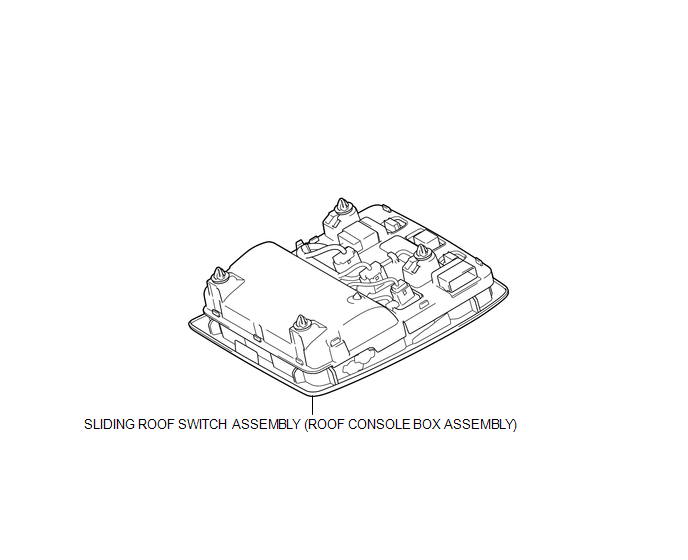
COMPONENTS
ILLUSTRATION
Installation
INSTALLATION
PROCEDURE
1. INSTALL SLIDING ROOF SWITCH ASSEMBLY (ROOF CONSOLE BOX ASSEMBLY)
(a) Connect the connector.
(b) Engage the 4 clips to install the sliding roof switch assembly (roof console box assembly).
Removal
REMOVAL
PROCEDURE
1. REMOVE SLIDING ROOF SWITCH ASSEMBLY (ROOF CONSOLE BOX ASSEMBLY)
|
(a) Using a moulding remover D, disengage the 4 clips to separate the sliding roof switch assembly (roof console box assembly). |
|
.png)
(b) Disconnect the connector to remove the sliding roof switch assembly (roof console box assembly).
 Removal
REMOVAL
PROCEDURE
1. REMOVE SLIDING ROOF SIDE GARNISH LH
(a) Fully open the sunshade trim sub-assembly.
(b) Remove the sliding roof side garnish LH.
...

Other materials:
Theft Deterrent System Unexpectedly Sets Itself
DESCRIPTION
A situation in which the theft deterrent system unexpectedly sets itself can
be caused when the main body ECU (multiplex network body ECU) cannot detect whether
a door is open or closed.
If the theft deterrent system unexpectedly sets itself, there may be a malfunction
in a court ...
Steering Angle Sensor (C1A47)
DESCRIPTION
The millimeter wave radar sensor assembly receives steering angle information
from the steering angle sensor (spiral cable with sensor sub-assembly). If the millimeter
wave radar sensor assembly detects a steering angle sensor (spiral cable with sensor
sub-assembly) malfunction, D ...
Installation
INSTALLATION
PROCEDURE
1. INSTALL TRANSFER ASSEMBLY
Click here
2. INSTALL WIRING HARNESS CLAMP BRACKET
(a) Install the 4 wiring harness clamp brackets with the 4 bolts.
Torque:
8.0 N·m {82 kgf·cm, 71 in·lbf}
3. INSTALL TRANSMISSION BREATHER SUB-ASSEMBLY
(a) Install the 2 brackets to t ...
