Toyota Tacoma (2015-2018) Service Manual: Removal
REMOVAL
PROCEDURE
1. PRECAUTION
NOTICE:
After turning the ignition switch off, waiting time may be required before disconnecting the cable from the negative (-) battery terminal.
Therefore, make sure to read the disconnecting the cable from the negative (-) battery terminal notices before proceeding with work.
Click here .gif)
2. DISCONNECT CABLE FROM NEGATIVE BATTERY TERMINAL
NOTICE:
When disconnecting the cable, some systems need to be initialized after the cable is reconnected.
Click here
3. REMOVE NO. 1 ENGINE UNDER COVER SUB-ASSEMBLY
4. REMOVE FAN AND GENERATOR V BELT
Click here
5. DRAIN POWER STEERING FLUID
6. DISCONNECT PRESSURE FEED TUBE ASSEMBLY
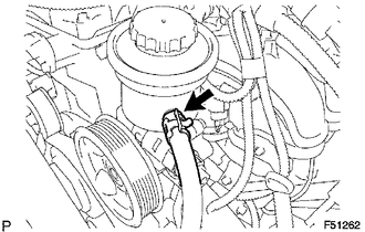
(a) Disengage the clip and disconnect the return hose.
|
(b) Remove the union bolt, then disconnect the pressure feed tube. |
|
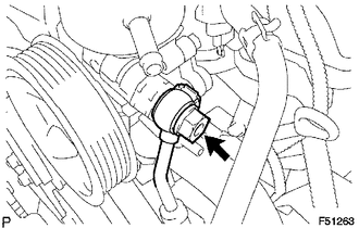
(c) Remove the gasket from the pressure feed tube.
7. REMOVE VANE PUMP
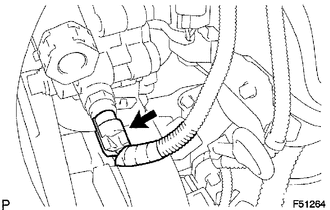
(a) Disconnect the oil pressure switch connector.
|
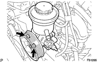
(b) Remove the 2 bolts and vane pump assembly. |
|
 Disassembly
DISASSEMBLY
PROCEDURE
1. FIX VANE PUMP
(a) Using SST, fix the vane pump assembly in a vise.
SST: 09630-00014
09631-00132
NOTICE:
When using a vise, do not overtighten it.
2. REMOVE VANE PUMP ...
 Inspection
INSPECTION
PROCEDURE
1. INSPECT OIL CLEARANCE
(a) Using a micrometer and caliper gauge, measure the oil seal clearance.
Standard clearance:
0.021 to 0.043 mm (0.0008 to 0.0017 in.)
Maximum cl ...
Other materials:
Skid Control Buzzer Circuit (C1A4A)
DESCRIPTION
The millimeter wave radar sensor assembly is connected to the forward recognition
camera via CAN communication.
The millimeter wave radar sensor assembly operates the pre-collision alarm by
sending a buzzer request signal to the skid control buzzer.
If the millimeter wave radar se ...
On-vehicle Inspection
ON-VEHICLE INSPECTION
PROCEDURE
1. INSPECT BRAKE MASTER CYLINDER FLUID PRESSURE CHANGE
(a) Inspect the battery positive voltage.
Battery positive voltage:
10 to 14 V
(b) Turn the ignition switch to OFF, and depress the brake pedal more than 20
times.
HINT:
When pressure in the accumulator ...
Disassembly
DISASSEMBLY
CAUTION / NOTICE / HINT
HINT:
The procedure described below is for the LH side. Use the same procedure for
both the LH and RH sides, unless otherwise specified.
PROCEDURE
1. REMOVE REAR SEATBACK COVER
(a) Remove the 2 screws.
...
