Toyota Tacoma (2015-2018) Service Manual: Removal
REMOVAL
PROCEDURE
1. REMOVE FRONT SEAT ASSEMBLY (for Driver Side)
(See page .gif) )
)
2. REMOVE FRONT SEAT ASSEMBLY (for Front Passenger Side)
(See page )
3. REMOVE SEPARATE TYPE FRONT SEAT CUSHION COVER (for Driver Side)
(See page )
4. REMOVE SEPARATE TYPE FRONT SEAT CUSHION COVER (for Front Passenger Side)
(See page )
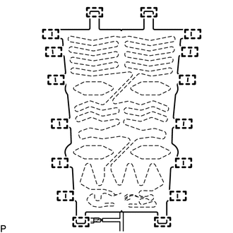
5. REMOVE FRONT SEAT CUSHION HEATER ASSEMBLY (for Driver Side)
|
(a) Cut off the 16 tag pins which fasten the front seat cushion heater assembly to the front seat cushion cover, and then remove the front seat cushion heater assembly from the front seat cushion cover. |
|
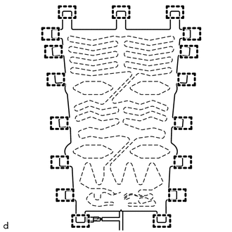
6. REMOVE FRONT SEAT CUSHION HEATER ASSEMBLY (for Front Passenger Side)
|
(a) Cut off the 17 tag pins which fasten the front seatcushion heater assembly to the front seat cushion cover, and then remove the front seat cushion heater assembly from the front seat cushion cover. |
|
 Inspection
INSPECTION
PROCEDURE
1. INSPECT FRONT SEAT CUSHION HEATER ASSEMBLY
(a) Check the operation of the front seat cushion heater assembly.
(1) Apply battery voltage and check the operation ...
 Installation
INSTALLATION
PROCEDURE
1. INSTALL FRONT SEAT CUSHION HEATER ASSEMBLY (for Driver Side)
(a) Set the front seat cushion heater assembly so that the name stamp side facing
is on the front seat cushi ...
Other materials:
Under Hood
General Maintenance
GENERAL MAINTENANCE
PROCEDURE
1. GENERAL NOTES
Maintenance items may vary from country to country. Check the owner's
manual supplement in which the maintenance schedule is shown.
Every service item in the periodic maintenance schedule must be performed.
...
Installation
INSTALLATION
PROCEDURE
1. INSTALL CLUTCH PEDAL NO.1 CUSHION
(a) Install the clutch pedal No. 1 cushion to the clutch pedal sub-assembly.
2. INSTALL CLUTCH PEDAL SHAFT COLLAR
(a) Apply MP grease to the clutch pedal shaft collar.
Text in Illustration
MP grease
(b) ...
Front Passenger Side Seat Heater does not Operate
DESCRIPTION
When the seat heater switch on the air conditioning control assembly is operated,
the air conditioning amplifier assembly receives the signal. The air conditioning
amplifier assembly receives the signal and operates the front seat heater.
WIRING DIAGRAM
CAUTION / NOTICE / HINT
...
