Toyota Tacoma (2015-2018) Service Manual: Disassembly
DISASSEMBLY
PROCEDURE
1. REMOVE BRAKE ACTUATOR BRACKET NO. 1
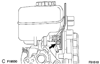
(a) Using a hexagon wrench (5 mm), remove the screw and brake actuator bracket No. 1.
|
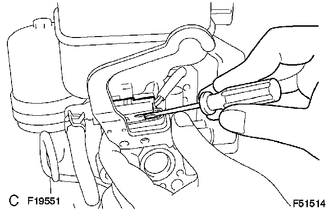
(b) Using a screwdriver, remove the fluid level warning switch connector. |
|
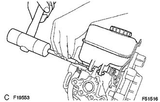
2. REMOVE BRAKE MASTER CYLINDER RESERVOIR SUB-ASSEMBLY
(a) Remove the screw from the master cylinder reservoir.
|
(b) Using a pin punch and hammer, remove the pin from the master cylinder reservoir. |
|
(c) Pull out the master cylinder reservoir.
(d) Remove the 3 grommets.
(e) Remove the cap.
3. REMOVE BRAKE ACTUATOR HOSE NO. 1
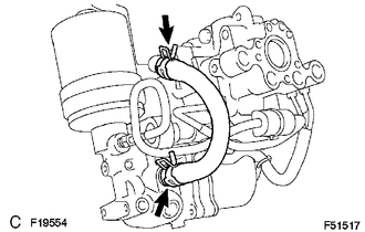
(a) Using needle-nose pliers, slide the 2 clips.
(b) Remove the brake actuator hose.
4. REMOVE BRAKE ACTUATOR TUBE NO. 1
(a) Using a union nut wrench, remove the brake actuator tube No. 1.
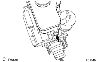
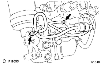
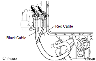
5. REMOVE BRAKE BOOSTER WITH ACCUMULATOR PUMP ASSEMBLY
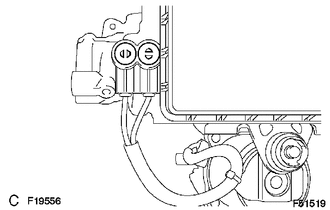
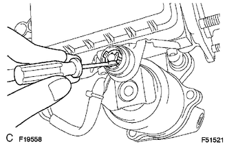
(a) Using a screwdriver, remove the 2 plugs.
|
(b) Remove the 2 screws and pull the wire harness. |
|
|
(c) Using a screwdriver, remove the clip. |
|
|
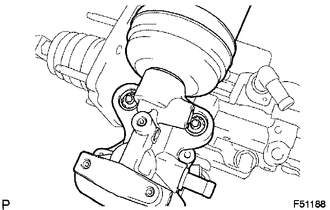
(d) Remove the brake booster w/ accumulator pump assembly. |
|
|
(e) Using a hexagon wrench (4 mm), remove the 2 pins. |
|
(f) Remove the 2 bushes and 2 collars from the brake booster with accumulator pump assembly.
6. REMOVE BRAKE ACTUATOR BRACKET
(a) Using a hexagon wrench (5 mm), remove the screw and brake actuator bracket.
7. REMOVE BRAKE BOOSTER PUMP BRACKET

(a) Using a hexagon wrench (5 mm), remove the 2 screws and brake booster pump bracket.
(b) Remove the bush from the brake booster pump bracket.
8. REMOVE MASTER CYLINDER PUSH ROD CLEVIS
(a) Loosen the lock nut on the brake master cylinder side, and then remove the rod operating adapter and lock nut.
(b) Loosen the lock nut on the rod operating adapter, and then remove the push rod clevis and lock nut.
9. REMOVE MASTER CYLINDER BOOT
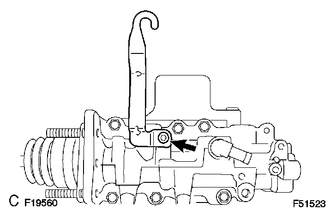
10. REMOVE PISTON
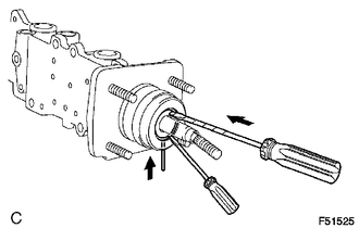
(a) Which pressing in the piston with a screwdriver, use a pin or equivalent to push the C-ring from the hole in the master cylinder body. Then remove the snap ring with another screwdriver.
(b) Remove the piston by pulling it straight out, not at an angle.
NOTICE:
- If the piston is pulled out at an angle, there is a possibility that the cylinder bore could be damaged.
- Be careful not to damage the rubber lips on the piston when reassembling.
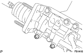
11. REMOVE MASTER CYLINDER SOLENOID
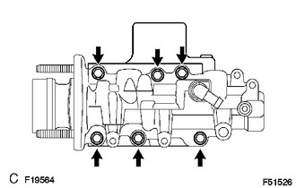
(a) Remove the 6 bolts.
(b) Remove the master cylinder solenoid and the gasket.
12. REMOVE BRAKE BOOSTER ACCUMULATOR ASSEMBLY
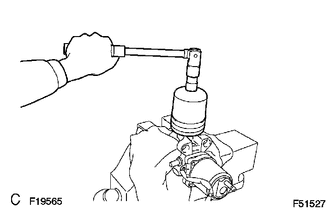
(a) Place the brake booster with accumulator pump assembly in a vise with a cloth.
(b) Using a socket wrench (17 mm), remove the brake booster accumulator.
(c) Remove the brake booster accumulator pipe, compression spring and O-ring.
 On-vehicle Inspection
ON-VEHICLE INSPECTION
PROCEDURE
1. INSPECT BRAKE MASTER CYLINDER FLUID PRESSURE CHANGE
(a) Inspect the battery positive voltage.
Battery positive voltage:
10 to 14 V
(b) Turn the ignition switc ...
 Removal
REMOVAL
CAUTION / NOTICE / HINT
NOTICE:
Before starting the work, make sure that the ignition switch is off
and depress the brake pedal more than 20 times.
As high pressure is appli ...
Other materials:
Entire Combination Meter does not Operate
DESCRIPTION
This circuit is the power source circuit for the meter. This circuit provides
two types of power sources, one is a constant power source mainly used as a backup
power source, and the other is an IG power source mainly used for signal transmission.
The constant power source is main ...
Open / Short in Steering Lock ECU (B2781)
DESCRIPTION
The steering lock ECU and steering lock motor are built into the steering lock
actuator assembly.
The steering lock ECU (steering lock actuator or UPR bracket assembly) detects
whether the steering lock is in the lock or unlock position by using the lock sensor
and unlock sensor ...
Precaution
PRECAUTION
1. PRECAUTION
(a) Before starting work on the fuel system, including inspections and repairs,
disconnect the cable from the negative (-) battery terminal.
(b) Do not smoke or work near fire when performing work on the fuel system.
(c) Keep gasoline away from rubber or leather parts. ...
