Toyota Tacoma (2015-2018) Service Manual: Disassembly
DISASSEMBLY
PROCEDURE
1. REMOVE PRESSURE RELIEF VALVE
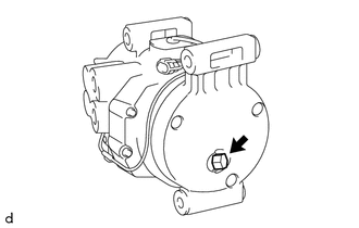
(a) Remove the pressure relief valve and O-ring.
2. REMOVE MAGNET CLUTCH ASSEMBLY
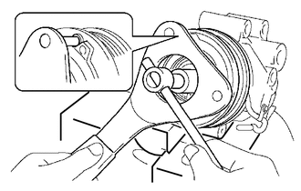
(a) Secure the cooler compressor assembly in a vise between aluminum plates.
(b) Using SST, hold the magnet clutch hub.
SST: 09985-00260
(c) Remove the bolt, magnet clutch hub and compressor spacer.
HINT:
There is no set number of magnet clutch washers since they are used for adjusting.
|
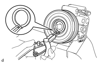
(d) Using a snap ring expander, remove the snap ring and magnet clutch rotor. NOTICE: Do not damage the seal cover of the bearing when removing the snap ring. |
|
|
(e) Remove the screw. |
|
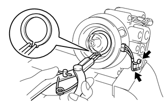
(f) Disconnect the connector.
(g) Using a snap ring expander, remove the snap ring and magnet clutch stator.
3. REMOVE COMPRESSOR PICK UP SENSOR
|
(a) Disengage the clamp. |
|
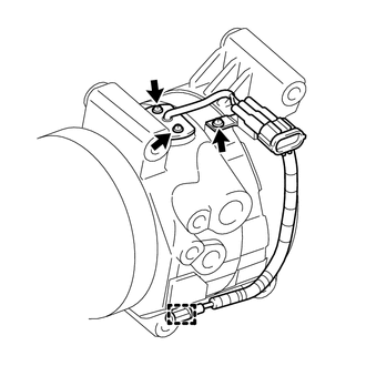
(b) Remove the 3 screws and compressor pick up sensor.
 Removal
REMOVAL
PROCEDURE
1. PRECAUTION
NOTICE:
After turning the ignition switch off, waiting time may be required before disconnecting
the cable from the negative (-) battery terminal. Therefore, make ...
 Inspection
INSPECTION
PROCEDURE
1. INSPECT MAGNET CLUTCH ASSEMBLY
(a) Inspect the magnet clutch assembly.
Text in Illustration
*a
Component without harness c ...
Other materials:
Tire Pressure Monitor ECU Communication Stop Mode
DESCRIPTION
Detection Item
Symptom
Trouble Area
Tire Pressure Monitor ECU Communication Stop Mode
Either condition is met:
Communication stop for "Tire Pressure2" is indicated on the
"Communication Bus C ...
Power outlet (120 VAC)∗
The power outlet can be used for electrical appliances.
Main switch
To use the power outlet, turn on the main switch.
The power supply starts a few seconds after the main switch is pressed.
Power outlet socket
Maximum available capacity of the power outlet
■ While the vehicle is being ...
Removal
REMOVAL
PROCEDURE
1. PRECAUTION
CAUTION:
Be sure to read Precaution thoroughly before servicing (See page
).
NOTICE:
After turning the ignition switch off, waiting time may be required before disconnecting
the cable from the negative (-) battery terminal. Therefore, make sure to read the
...
