Toyota Tacoma (2015-2018) Service Manual: Inspection
INSPECTION
PROCEDURE
1. INSPECT FRONT SEAT CUSHION HEATER ASSEMBLY
|
(a) Check the operation of the front seat cushion heater assembly. (1) Apply battery voltage and check the operation of the front seat cushion heater assembly. OK:
NOTICE: Immediately after confirming that the front seat cushion heater assembly is functioning normally, remove the battery leads. Failing to do so may cause the front seat cushion heater assembly to overheat. If the result is not as specified, replace the front seat cushion heater assembly. |
|
(b) Check the operation of the thermostat.
(1) Apply battery voltage and check the operation of the front seat cushion heater assembly.
OK:
|
Connection |
Condition |
Specified Condition |
|---|---|---|
|
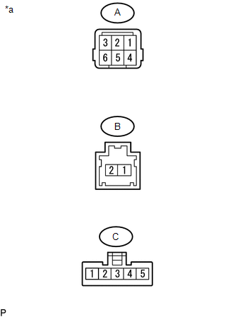
Battery positive (+) → Terminal A-3 Battery negative (-) → Terminal C-5 |
Always |
Seat cushion heater temperature becomes below 55°C (129°F) |
NOTICE:
Immediately after confirming that the front seat cushion heater assembly is functioning normally, remove the battery leads. Failing to do so may cause the front seat cushion heater assembly to overheat.
If the result is not as specified, replace the front seat cushion heater assembly.
(c) Check the resistance.
(1) Measure the resistance according to the value(s) in the table below.
Standard Resistance:
|
Tester Connection |
Connection |
Specified Condition |
|---|---|---|
|
A-1 - C-3 |
Always |
Below 1 Ω |
|
A-2 - C-1 |
Always |
Below 1 Ω |
|
A-5 - C-5 - B-2 |
Always |
Below 1 Ω |
 Components
COMPONENTS
ILLUSTRATION
*A
for Driver Side
-
-
*1
FRONT SEAT CUSHION HEATER ASSEMBLY
*2
SEPARATE TYPE ...
 Removal
REMOVAL
PROCEDURE
1. REMOVE FRONT SEAT ASSEMBLY (for Driver Side)
(See page )
2. REMOVE FRONT SEAT ASSEMBLY (for Front Passenger Side)
(See page )
3. REMOVE SEPARATE TYPE FRONT SEAT CUSHION CO ...
Other materials:
Steering Angle Sensor Internal Circuit (C1433)
DESCRIPTION
Steering angle sensor (spiral cable with sensor sub-assembly) signals are sent
to the skid control ECU (master cylinder solenoid) via the CAN communication system.
When there is a malfunction in the CAN communication system, it is detected by the
steering angle sensor (spiral cabl ...
Precaution
PRECAUTION
1. BASIC REPAIR HINT
(a) HINTS ON OPERATIONS
1
Attire
Always wear a clean uniform.
A hat and safety shoes must be worn.
2
Vehicle protection
Prepare a grille cover, fe ...
How To Proceed With Troubleshooting
CAUTION / NOTICE / HINT
HINT:
The ECM of this system is connected to the CAN communication system.
Therefore, before starting troubleshooting, make sure to check that there
is no trouble in the CAN and multiplex communication system.
*: Use the Techstream.
PROCEDURE
...
