Toyota Tacoma (2015-2018) Service Manual: Removal
REMOVAL
CAUTION / NOTICE / HINT
HINT:
- Use the same procedure for the RH side and LH side.
- The following procedure is for the LH side.
PROCEDURE
1. PRECAUTION
NOTICE:
After turning the ignition switch off, waiting time may be required before disconnecting the cable from the negative (-) battery terminal. Therefore, make sure to read the disconnecting the cable from the negative (-) battery terminal notices before proceeding with work.
Click here .gif)
2. DISCONNECT CABLE FROM NEGATIVE BATTERY TERMINAL
NOTICE:
When disconnecting the cable, some systems need to be initialized after the cable is reconnected.
Click here
3. REMOVE REAR DOOR FRAME GARNISH
Click here
4. REMOVE REAR DOOR INSIDE HANDLE BEZEL PLUG
Click here
5. REMOVE REAR DOOR ARMREST BASE UPPER PANEL
Click here
6. REMOVE REAR DOOR TRIM BOARD SUB-ASSEMBLY
Click here
7. REMOVE NO. 1 DOOR TRIM BRACKET
Click here
8. REMOVE REAR DOOR SERVICE HOLE COVER
Click here
9. REMOVE NO. 2 REAR DOOR SERVICE HOLE COVER
Click here
10. REMOVE HOLE PLUG
Click here
11. REMOVE REAR DOOR WINDOW REAR LOWER FRAME SUB-ASSEMBLY
Click here
12. REMOVE REAR DOOR GLASS RUN
Click here
13. REMOVE REAR DOOR GLASS SUB-ASSEMBLY
Click here
14. REMOVE REAR DOOR GLASS OUTER WEATHERSTRIP
|
(a) Put protective tape around the rear door belt moulding assembly. |
|
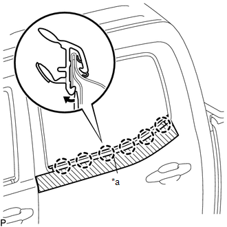
(b) Using a screwdriver, disengage the 6 claws to remove the rear door glass outer weatherstrip.
 Installation
INSTALLATION
CAUTION / NOTICE / HINT
HINT:
Use the same procedure for the RH side and LH side.
The following procedure is for the LH side.
PROCEDURE
1. INSTALL REAR DOOR GLASS O ...
 Rear Door Black Out Tape
Components
COMPONENTS
ILLUSTRATION
Installation
INSTALLATION
CAUTION / NOTICE / HINT
HINT:
Use the same procedure for the RH and LH sides.
The procedure described below is for ...
Other materials:
Lost Communication With ECM/PCM "A" Missing Message (U010087)
DESCRIPTION
The engine control unit and transmission control unit are located inside the
ECM. The engine control unit intercommunicates with the transmission control ECU
via CAN communication. If there is a problem in this intercommunication, the ECM
stores this DTC.
DTC Code
...
Removal
REMOVAL
CAUTION / NOTICE / HINT
PROCEDURE
1. PRECAUTION
CAUTION:
Be sure to read Precaution thoroughly before servicing (See page
).
NOTICE:
After turning the ignition switch off, waiting time may be required before disconnecting
the cable from the negative (-) battery terminal. Therefore ...
Glass Position Initialization Incomplete (B2313)
DESCRIPTION
The power window regulator motor assembly is operated by the power window regulator
master switch assembly or power window regulator switch assembly. The power window
regulator motor assembly has motor, regulator and ECU functions.
When the ECU determines that the power window regu ...
