Toyota Tacoma (2015-2018) Service Manual: Installation
INSTALLATION
CAUTION / NOTICE / HINT
HINT:
- Use the same procedure for the RH side and LH side.
- The following procedure is for the LH side.
PROCEDURE
1. INSTALL REAR DOOR GLASS OUTER WEATHERSTRIP
|
(a) Engage the 6 claws to install the rear door glass outer weatherstrip. |
|
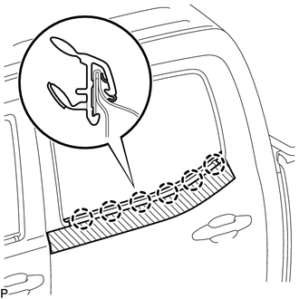
(b) Remove the protective tape.
2. INSTALL REAR DOOR GLASS SUB-ASSEMBLY
Click here .gif)
3. INSTALL REAR DOOR GLASS RUN
Click here
4. INSTALL REAR DOOR WINDOW REAR LOWER FRAME SUB-ASSEMBLY
Click here
5. INSTALL HOLE PLUG
Click here
6. INSTALL NO. 2 REAR DOOR SERVICE HOLE COVER
Click here
7. INSTALL REAR DOOR SERVICE HOLE COVER
Click here
8. INSTALL NO. 1 DOOR TRIM BRACKET
Click here
9. INSTALL REAR DOOR TRIM BOARD SUB-ASSEMBLY
Click here
10. INSTALL REAR DOOR ARMREST BASE UPPER PANEL
Click here
11. INSTALL REAR DOOR INSIDE HANDLE BEZEL PLUG
Click here
12. INSTALL REAR DOOR FRAME GARNISH
Click here
13. CONNECT CABLE TO NEGATIVE BATTERY TERMINAL
Torque:
5.4 N·m {55 kgf·cm, 48 in·lbf}
NOTICE:
When disconnecting the cable, some systems need to be initialized after the cable is reconnected.
Click here
14. INSPECT POWER WINDOW OPERATION
Click here
 Components
COMPONENTS
ILLUSTRATION
ILLUSTRATION
ILLUSTRATION
...
 Removal
REMOVAL
CAUTION / NOTICE / HINT
HINT:
Use the same procedure for the RH side and LH side.
The following procedure is for the LH side.
PROCEDURE
1. PRECAUTION
NOTICE:
After tur ...
Other materials:
Black Screen
PROCEDURE
1.
CHECK DISPLAY SETTING
(a) Check that the display is not in "Screen Off" mode.
OK:
The display setting is not in "Screen Off" mode.
NG
CHANGE SCREEN TO SCREEN ON MODE
OK
...
On-vehicle Inspection
ON-VEHICLE INSPECTION
PROCEDURE
1. INSPECT CAMSHAFT TIMING OIL CONTROL SOLENOID ASSEMBLY (for Intake Side)
(a) Connect the Techstream to the DLC3.
(b) Start the engine.
(c) Turn the Techstream on.
(d) Enter the following menus: Powertrain / Engine / Active Test / Control the
Intake VVT OCV D ...
Tonneau Cover Assembly
Removal
REMOVAL
PROCEDURE
1. REMOVE TOP COVER SUB-ASSEMBLY
(a) Open the cover.
(b) Remove the bolt and top cover sub-assembly.
2. REMOVE REAR BODY SIDE PANEL PROTECTOR
Click here
Installation
INSTALLATION
PROCEDURE
1. INSTALL REAR ...
