Toyota Tacoma (2015-2018) Service Manual: Neutral Position Switch
Components
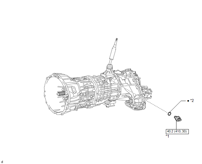
COMPONENTS
ILLUSTRATION
|
*1 |
NEUTRAL POSITION SWITCH |
*2 |
GASKET |
.png) |
N*m (kgf*cm, ft.*lbf): Specified torque |
â—Ź |
Non-reusable part |
Installation
INSTALLATION
PROCEDURE
1. INSTALL NEUTRAL POSITION SWITCH
|
(a) Using SST, install the neutral position switch and a new gasket to the transmission case. SST: 09817-16011 Torque: 40.2 N·m {410 kgf·cm, 30 ft·lbf} |
|
(b) Connect the connector.
Removal
REMOVAL
PROCEDURE
1. REMOVE NEUTRAL POSITION SWITCH
|
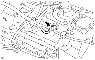
(a) Disconnect the connector. |
|
|
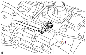
(b) Using SST, remove the neutral position switch and gasket from the transmission case. SST: 09817-16011 |
|
.png)
 Manual Transmission Unit
Components
COMPONENTS
ILLUSTRATION
ILLUSTRATION
*1
SHIFT DETENT BALL PLUG
*2
SHIFT DETENT BALL COMPRESSION SPRING
*3
M ...
 Output Shaft
Components
COMPONENTS
ILLUSTRATION
Disassembly
DISASSEMBLY
PROCEDURE
1. REMOVE FRONT OUTPUT SHAFT BEARING
(a) Temporarily install the manual transmission output shaft rear set ...
Other materials:
Drive Belt
Components
COMPONENTS
ILLUSTRATION
Precaution
PRECAUTION
NOTICE:
Do not apply or add oil or grease to the belt tensioner to prevent abnormal
noises from the belt tensioner pulley, belt squealing, etc.
Do not allow oil or grease to adhere to the moving parts of the belt
...
How To Proceed With Troubleshooting
CAUTION / NOTICE / HINT
HINT:
Use these procedures to troubleshoot the lighting system.
*: Use the Techstream.
PROCEDURE
1.
VEHICLE BROUGHT TO WORKSHOP
NEXT
2.
...
Disassembly
DISASSEMBLY
PROCEDURE
1. REMOVE STEERING INTERMEDIATE SHAFT ASSEMBLY
(a) Put matchmarks on the steering intermediate shaft assembly and steering main
shaft assembly.
(b) Remove the bolt and steering intermediate shaft assembly.
2. REMOVE UPPER STEERING COLUMN BRACKET WITH SWITCH ASSEMBLY (w ...
