Toyota Tacoma (2015-2018) Service Manual: Transponder Key Amplifier
Components
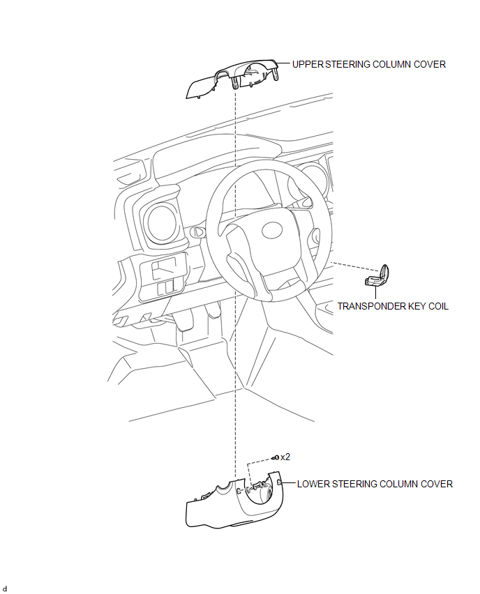
COMPONENTS
ILLUSTRATION
Installation
INSTALLATION
PROCEDURE
1. INSTALL TRANSPONDER KEY COIL
|
(a) Engage the 2 claws to install the transponder key coil. |
|
(b) Connect the connector.
2. INSTALL UPPER STEERING COLUMN COVER
(See page .gif) )
)
3. INSTALL LOWER STEERING COLUMN COVER
(See page
)
Removal
REMOVAL
PROCEDURE
1. REMOVE LOWER STEERING COLUMN COVER
(See page .gif) )
)
2. REMOVE UPPER STEERING COLUMN COVER
(See page
)
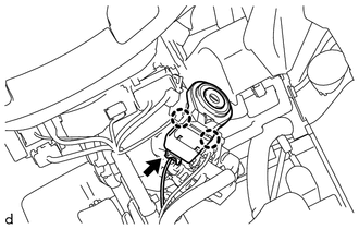
3. REMOVE TRANSPONDER KEY COIL
|
(a) Disconnect the connector. |
|
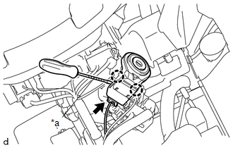
(b) Using a screwdriver with its tip wrapped in protective tape, disengage the 2 claws to remove the transponder key coil.
Text in Illustration|
*a |
Protective Tape |
 Security Indicator Light Does not Blink
DESCRIPTION
The transponder key ECU assembly blinks the security indicator light
when the immobiliser is set (no key is in the ignition key cylinder).
w/ Theft Deterrent System:
...
 Transponder Key Ecu
Components
COMPONENTS
ILLUSTRATION
Installation
INSTALLATION
PROCEDURE
1. INSTALL TRANSPONDER KEY ECU
(a) Engage the 2 guides to move the transponder key ECU in the direction
...
Other materials:
Clutch Pedal Switch
On-vehicle Inspection
ON-VEHICLE INSPECTION
PROCEDURE
1. CHECK CLUTCH START SYSTEM
(a) Check that the engine does not start when the clutch pedal is released.
(b) Check that the engine starts when the clutch pedal is fully depressed.
If necessary, replace the clutch start switch assembly.
...
Brake Booster Pump Motor on Time Abnormally Long (C1252)
DESCRIPTION
The motor relay (semiconductor relay) is built into the master cylinder solenoid
and drives the pump motor based on a signal from the skid control ECU (master cylinder
solenoid).
DTC No.
DTC Detecting Condition
Trouble Areas
C1252
...
Customize Parameters
CUSTOMIZE PARAMETERS
1. LANE DEPARTURE ALERT SYSTEM
Click here
2. INTUITIVE PARKING ASSIST SYSTEM
Click here
3. PRE-COLLISION SYSTEM
Click here
4. SEAT BELT WARNING SYSTEM
Click here
5. AIR CONDITIONING SYSTEM (for Automatic Air Conditioning System)
Click here
6. THEFT DETERRENT ...
