Toyota Tacoma (2015-2018) Service Manual: Output Shaft
Components
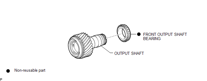
COMPONENTS
ILLUSTRATION
Disassembly
DISASSEMBLY
PROCEDURE
1. REMOVE FRONT OUTPUT SHAFT BEARING
|
(a) Temporarily install the manual transmission output shaft rear set nut to the output shaft. Text in Illustration
|
|
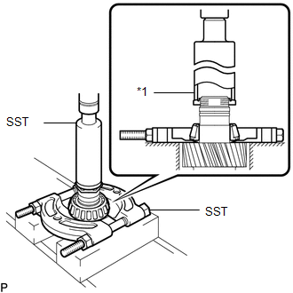
(b) Using SST and a press, remove the front output shaft bearing from the output shaft.
SST: 09316-60011
09316-00011
SST: 09950-00020
Inspection
INSPECTION
PROCEDURE
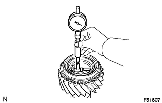
1. INSPECT OUTPUT SHAFT
|
(a) Using a cylinder gauge, measure the inside diameter of the output shaft. Standard inside diameter: 45.009 to 45.025 mm (1.77201 to 1.7726 in.) Maximum inside diameter: 45.025 mm (1.7726 in.) If the diameter is more than the maximum, replace the output shaft. |
|
Reassembly
REASSEMBLY
PROCEDURE
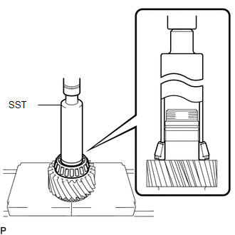
1. INSTALL FRONT OUTPUT SHAFT BEARING
|
(a) Using SST and a press, install a new front output shaft bearing to the output shaft. SST: 09316-60011 09316-00011 |
|
 Neutral Position Switch
Components
COMPONENTS
ILLUSTRATION
*1
NEUTRAL POSITION SWITCH
*2
GASKET
N*m (kgf*cm, ft.*lbf): Specified torque
...
 Suspension
...
Other materials:
Power Source Mode does not Change to ON (IG and ACC)
DESCRIPTION
If any of the following operations are performed, the certification ECU (smart
key ECU assembly) receives a signal, and changes the power source mode.
With the electrical key transmitter sub-assembly in the cabin, the engine
switch is pressed.
When the battery of the e ...
Engine Coolant Temperature Sensor
Components
COMPONENTS
ILLUSTRATION
Inspection
INSPECTION
PROCEDURE
1. INSPECT ENGINE COOLANT TEMPERATURE SENSOR
(a) Partially immerse the engine coolant temperature sensor in water and warm
up the water.
(b) Measure the resistance according to the value(s) in the table bel ...
Open / Short in Steering Lock ECU (B2781)
DESCRIPTION
The steering lock ECU and steering lock motor are built into the steering lock
actuator assembly.
The steering lock ECU (steering lock actuator or UPR bracket assembly) detects
whether the steering lock is in the lock or unlock position by using the lock sensor
and unlock sensor ...
