Toyota Tacoma (2015-2018) Service Manual: Main Switch Circuit
DESCRIPTION
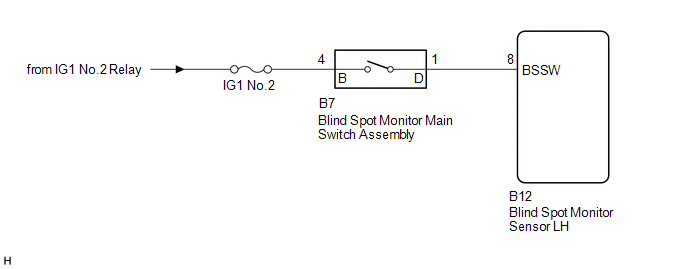
When the blind spot monitor main switch assembly (warning canceling switch assembly) is turned on, a signal is sent to the blind spot monitor sensor LH. The blind spot monitor system operates according to this signal.
WIRING DIAGRAM
CAUTION / NOTICE / HINT
NOTICE:
Inspect the fuse for circuits related to this system before performing the following inspection procedure.
PROCEDURE
|
1. |
READ VALUE USING TECHSTREAM (MAIN SW) |
(a) Connect the Techstream to the DLC3.
(b) Turn the ignition switch to ON.
(c) Turn the Techstream on.
(d) Enter the following menus: Body Electrical / Blind Spot Monitor Master / Data List.
(e) According to the display on the Techstream, read the Data List.
Blind Spot Monitor Master|
Techstream Display |
Measurement Item/Range |
Normal Condition |
Diagnostic Note |
|---|---|---|---|
|
Main SW |
Blind spot monitor main switch assembly / OFF or ON |
ON: Blind spot monitor main switch assembly on OFF: Blind spot monitor main switch assembly off |
- |
|
Result |
Proceed to |
|---|---|
|
The display changes as shown above when the blind spot monitor main switch assembly is operated. |
A |
|
The display does not change as shown above when the blind spot monitor main switch assembly is operated. |
B |
| A | .gif) |
PROCEED TO NEXT SUSPECTED AREA SHOWN IN PROBLEM SYMPTOMS TABLE |
|
.gif)
|
2. |
INSPECT BLIND SPOT MONITOR MAIN SWITCH ASSEMBLY |
(a) Remove the blind spot monitor main switch assembly (See page
.gif) ).
).
(b) Inspect the blind spot monitor main switch assembly (See page
).
| NG | |
REPLACE BLIND SPOT MONITOR MAIN SWITCH ASSEMBLY |
|
|
3. |
CHECK HARNESS AND CONNECTOR (BLIND SPOT MONITOR MAIN SWITCH ASSEMBLY - BATTERY) |
|
(a) Disconnect the blind spot monitor main switch assembly connector. |
|
(b) Measure the voltage according to the value(s) in the table below.
Standard Voltage:
|
Tester Connection |
Switch Condition |
Specified Condition |
|---|---|---|
|
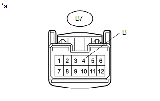
B7-4 (B) - Body ground |
Ignition switch ON |
11 to 14 V |
|
B7-4 (B) - Body ground |
Ignition switch off |
Below 1 V |
|
*a |
Front view of wire harness connector (to Blind Spot Monitor Main Switch Assembly) |
| NG | |
REPAIR OR REPLACE HARNESS OR CONNECTOR |
|
|
4. |
CHECK HARNESS AND CONNECTOR (BLIND SPOT MONITOR MAIN SWITCH ASSEMBLY - BLIND SPOT MONITOR SENSOR LH) |
(a) Disconnect the B12 blind spot monitor sensor LH connector.
(b) Disconnect the B7 blind spot monitor main switch assembly connector.
(c) Measure the resistance according to the value(s) in the table below.
Standard Resistance:
|
Tester Connection |
Condition |
Specified Condition |
|---|---|---|
|
B12-8 (BSSW) - B7-1 (D) |
Always |
Below 1 Ω |
|
B12-8 (BSSW) - Body ground |
Always |
10 kΩ or higher |
| OK | |
REPLACE BLIND SPOT MONITOR SENSOR LH |
| NG | |
REPAIR OR REPLACE HARNESS OR CONNECTOR |
 Master Module Horizontal Axis Misalignment (C1AC1)
DESCRIPTION
This DTC is stored when the angle of the blind spot monitor sensor LH deviates
more than the allowable range from the horizontal axis.
HINT:
If drum tester such as a speedometer teste ...
 Power Source Circuit
DESCRIPTION
This circuit provides power to operate the blind spot monitor sensor.
WIRING DIAGRAM
CAUTION / NOTICE / HINT
NOTICE:
Inspect the fuses for circuits related to this system before per ...
Other materials:
Inspection
INSPECTION
PROCEDURE
1. INSPECT OIL CLEARANCE
(a) Using a micrometer and caliper gauge, measure the oil seal clearance.
Text in Illustration
*1
Pulley Shaft
*2
Front Vane Pump Housing
...
Touch Panel Switch does not Function
PROCEDURE
1.
CHECK MULTI-DISPLAY
(a) Check if there is any foreign matter caught between the display and exterior
frame of the multi-display.
OK:
No foreign matter is caught between the display and exterior frame of the multi-display.
HINT:
If there is foreig ...
Lost Communication with ECM / PCM "A" (U0100,U0126,U0129,U0142)
DESCRIPTION
These DTCs are stored if there is a malfunction in the CAN communication system
connected to the blind spot monitor sensor.
HINT:
If CAN communication system DTCs are stored, they may also be stored for other
systems.
DTC Code
DTC Detection Condition
...
