Toyota Tacoma (2015-2018) Service Manual: Inspection
INSPECTION
PROCEDURE
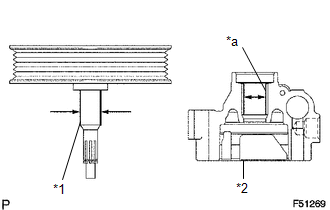
1. INSPECT OIL CLEARANCE
|
(a) Using a micrometer and caliper gauge, measure the oil seal clearance. Text in Illustration
Standard clearance: 0.021 to 0.043 mm (0.0008 to 0.0017 in.) Maximum clearance: 0.07 mm (0.0028 in.) If it is greater than the maximum, replace the vane pump assembly. |
|
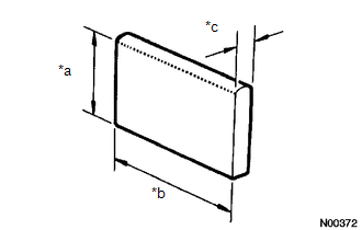
2. INSPECT VANE PUMP ROTOR AND VANE PUMP PLATE
|
(a) Using a micrometer, measure the height, thickness and length of the vane pump plates. Text in Illustration
Minimum height: 7.7 mm (0.303 in.) Minimum thickness: 1.408 mm (0.0554 in.) Minimum length: 11.993 mm (0.4722 in.) |
|
|
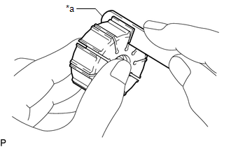
(b) Using a feeler gauge, measure the clearance between a side face of the vane pump rotor groove and vane pump plate. Text in Illustration
Maximum clearance: 0.025 mm (0.0012 in.) If it is greater than the maximum, replace the vane pump assembly. |
|
3. INSPECT FLOW CONTROL VALVE
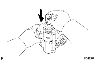
(a) Coat the flow control valve with power steering fluid and check that it falls smoothly into the flow control valve hole under its own weight.
|
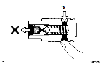
(b) Check the flow control valve for leakage. Close one of the holes and apply compressed air of 392 to 490 kPa (4.0 to 5.0 kgf/cm2, 57 to 71 psi) to the hole on the opposite side. Confirm that the air does not flow out of the end holes. Text in Illustration
If necessary, replace the vane pump assembly. |
|
4. INSPECT COMPRESSION SPRING
|
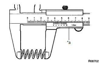
(a) Using a vernier caliper, measure the free length of the spring. Text in Illustration
Minimum free length: 36.9 mm (1.453 in.) If it is not within the specification, replace the vane pump assembly. |
|
5. INSPECT PRESSURE PORT UNION SUB-ASSEMBLY
(a) If the union seat in the pressure port union sub-assembly is badly damaged, it could cause fluid leakage, so replace the vane pump assembly.
 Removal
REMOVAL
PROCEDURE
1. REMOVE NO. 2 ENGINE UNDER COVER SUB-ASSEMBLY (w/ Off Road Package)
2. REMOVE NO. 1 ENGINE UNDER COVER SUB-ASSEMBLY
3. REMOVE FAN AND GENERATOR V BELT
4. DRAIN POWER STEERI ...
 Installation
INSTALLATION
PROCEDURE
1. INSTALL VANE PUMP ASSEMBLY
(a) Install the vane pump assembly with the 2 bolts.
Torque:
21 N·m {214 kgf·cm, 15 ft·lbf}
(b) Connect the ground wire with the bolt.
T ...
Other materials:
Removal
REMOVAL
PROCEDURE
1. PRECAUTION
NOTICE:
After turning the ignition switch off, waiting time may be required before disconnecting
the cable from the negative (-) battery terminal. Therefore, make sure to read the
disconnecting the cable from the negative (-) battery terminal notices before pr ...
Key information
The following keys are provided with the vehicle.
Vehicles without engine immobilizer
system
Master keys
Key number plate
Vehicles with engine immobilizer
system
Master keys
Key number plate
■Key number plate
Keep the plate in a safe place such as your wallet, not in the v ...
Front Occupant Classification Sensor LH Circuit Malfunction (B1780)
DESCRIPTION
The occupant classification sensor front LH circuit consists of the occupant
detection ECU and the occupant classification sensor front LH.
DTC B1780 is set when a malfunction is detected in the occupant classification
sensor front LH circuit.
DTC No.
DTC Det ...
