Toyota Tacoma (2015-2018) Service Manual: Components
COMPONENTS
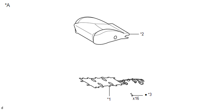
ILLUSTRATION
|
*A |
for Driver Side |
- |
- |
|
*1 |
FRONT SEAT CUSHION HEATER ASSEMBLY |
*2 |
SEPARATE TYPE FRONT SEAT CUSHION COVER |
|
*3 |
TAG PIN |
- |
- |
|
â—Ź |
Non-reusable part |
- |
- |
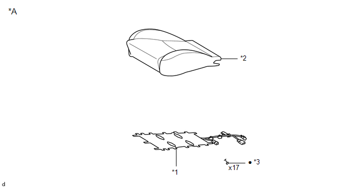
ILLUSTRATION
|
*A |
for Front Passenger Side |
- |
- |
|
*1 |
FRONT SEAT CUSHION HEATER ASSEMBLY |
*2 |
SEPARATE TYPE FRONT SEAT CUSHION COVER |
|
*3 |
TAG PIN |
- |
- |
|
â—Ź |
Non-reusable part |
- |
- |

 Inspection
INSPECTION
PROCEDURE
1. INSPECT FRONT SEAT CUSHION HEATER ASSEMBLY
(a) Check the operation of the front seat cushion heater assembly.
(1) Apply battery voltage and check the operation ...
Other materials:
Engine does not Start
DESCRIPTION
When the key is in the vehicle and the engine switch is pressed, the certification
ECU (smart key ECU assembly) receives a signal and changes the power source mode.
In addition, when the shift lever is in P or N and the brake pedal is depressed,
the engine can be started by pressi ...
Installation
INSTALLATION
PROCEDURE
1. INSTALL DIFFERENTIAL SIDE GEAR SHAFT OIL SEAL
(a) Using SST and a hammer, install a new oil seal.
SST: 09554-30011
(b) Coat the oil seal lip with MP grease.
2. INSTALL FRONT DRIVE SHAFT ASSEMBLY LH
Click here
3. INSTALL FRONT DRIVE SHAFT ASSEMBLY RH
HINT:
Use ...
Front Speed Sensor
Removal
REMOVAL
PROCEDURE
1. PRECAUTION
NOTICE:
After turning the ignition switch off, waiting time may be required before disconnecting
the cable from the negative (-) battery terminal.
Therefore, make sure to read the disconnecting the cable from the negative (-)
battery terminal notic ...
