Toyota Tacoma (2015-2018) Service Manual: Front Left Seat Heat Sensor Circuit (B14C1)
DESCRIPTION
Output to the front seat cushion heater assembly LH temperature sensor stops if one of the following occurs: 1) the temperature sensor is open or shorted; or 2) the temperature sensor is damaged and its output value does not change.
|
DTC Code |
DTC Detection Condition |
Trouble Area |
|---|---|---|
|
B14C1 |
Seat heater temperature sensor malfunction |
|
WIRING DIAGRAM
PROCEDURE
|
1. |
CLEAR DTC |
(a) Clear the DTCs (See page .gif) ).
).
|
.gif)
|
2. |
CHECK FOR DTC |
(a) Check for DTCs (See page ).
OK:
DTC B14C1 is not output.
| OK | .gif) |
USE SIMULATION METHOD TO CHECK |
|
|
3. |
READ VALUE USING TECHSTREAM |
(a) Connect the Techstream to the DLC3.
(b) Turn the ignition switch to ON.
(c) Turn the Techstream on.
(d) Enter the following menus: Body Electrical / Air Conditioner / Data List.
(e) Check the value(s) by referring to the table below.
Air Conditioner:
|
Tester Display |
Measurement Item/Range |
Normal Condition |
Diagnostic Note |
|---|---|---|---|
|
FL Seat Heater Temperature |
Front seat LH side seat heater temperature / min: -29.7°C or max: 59.55°C |
Within range from 36 to 42.2°C (96 to 108°F) |
Front seat heater is on |
OK:
The display is as specified in the normal condition column.
Result|
Result |
Proceed to |
|---|---|
|
NG |
A |
|
OK |
B |
| B | |
REPLACE AIR CONDITIONING AMPLIFIER ASSEMBLY |
|
|
4. |
INSPECT FRONT SEAT CUSHION HEATER ASSEMBLY LH |
(a) Remove the front seat cushion heater assembly LH (See page
).
(b) Inspect the front seat cushion heater assembly LH (See page
).
| NG | |
REPLACE FRONT SEAT CUSHION HEATER ASSEMBLY LH |
|
|
5. |
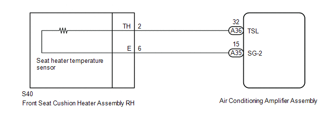
CHECK HARNESS AND CONNECTOR (AIR CONDITIONING AMPLIFIER ASSEMBLY - FRONT SEAT CUSHION HEATER ASSEMBLY LH) |
(a) Disconnect the A35 and A36 air conditioning amplifier assembly connector.
(b) Measure the resistance according to the value(s) in the table below.
Standard Resistance:
|
Tester Connection |
Condition |
Specified Condition |
|---|---|---|
|
A36-32 (TSL) - S40-2 (TH) |
Always |
Below 1 Ω |
|
A35-15 (SG-2) - S40-6 (E) |
Always |
Below 1 Ω |
|
A36-32 (TSL) - Body ground |
Always |
10 kΩ or higher |
|
A35-15 (SG-2) - Body ground |
Always |
10 kΩ or higher |
| OK | |
REPLACE AIR CONDITIONING AMPLIFIER ASSEMBLY |
| NG | |
REPAIR OR REPLACE HARNESS OR CONNECTOR |
 Front Right Seat Heat Sensor Circuit (B14C0)
DESCRIPTION
Output to the front seat cushion heater assembly RH temperature sensor stops
if one of the following occurs: 1) the temperature sensor is open or shorted; or
2) the temperature sensor ...
 Driver Side Seat Heater does not Operate
DESCRIPTION
When the seat heater switch on the air conditioning control assembly is operated,
the air conditioning amplifier assembly receives the signal. The air conditioning
amplifier assembly ...
Other materials:
Open / Short in Steering Lock ECU (B2781)
DESCRIPTION
The steering lock ECU and steering lock motor are built into the steering lock
actuator assembly.
The steering lock ECU (steering lock actuator or UPR bracket assembly) detects
whether the steering lock is in the lock or unlock position by using the lock sensor
and unlock sensor ...
Disassembly
DISASSEMBLY
PROCEDURE
1. REMOVE BRAKE ACTUATOR BRACKET NO. 1
(a) Using a hexagon wrench (5 mm), remove the screw and brake actuator bracket
No. 1.
(b) Using a screwdriver, remove the fluid level warning switch connector.
2. REMOVE BRAKE M ...
Side Airbag Sensor LH Circuit Malfunction (B1625/22)
DESCRIPTION
The side airbag sensor assembly LH consists of parts such as the safing sensor,
the diagnostic circuit and the lateral deceleration sensor.
When the airbag sensor assembly receives signals from the lateral deceleration
sensor, it determines whether or not the SRS should be activate ...
