Toyota Tacoma (2015-2018) Service Manual: Adjustment
ADJUSTMENT
PROCEDURE
1. INSPECT AND ADJUST CLUTCH PEDAL
(a) Fold back the floor carpet.
|
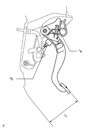
(b) Check that the pedal height is correct. Text in Illustration
Pedal height from floor panel: 178.1 to 188.1 mm (7.01 to 7.41 in.) |
|
(c) Adjust the pedal height.
(1) Loosen the lock nut and turn the clutch switch assembly until the height is correct. Tighten the lock nut.
Torque:
20 N·m {201 kgf·cm, 15 ft·lbf}
|
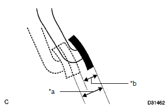
(d) Check the pedal free play and push rod play. Text in Illustration
HINT: Pay close attention to the change in resistance to distinguish between pedal free play and push rod play while performing the inspection. (1) Depress the clutch pedal until resistance is felt. (2) Measure the distance between the pedal's released position and the position in the previous step. Pedal free play: 5.0 to 15.0 mm (0.197 to 0.591 in.) (3) Release the pedal. Using your finger, gently press the pedal until resistance increases slightly. (4) Measure the distance between the pedal's released position and the position in the previous step. Push rod play at pedal top: 1.0 to 5.0 mm (0.0394 to 0.197 in.) |
|
(e) Adjust the pedal free play and push rod play.
HINT:
The push rod play can be adjusted by changing the length of the push rod. Pedal free play changes together with push rod play.
(1) Loosen the lock nut and turn the push rod until the pedal free play and push rod play are within the specified ranges.
NOTICE:
If pedal free play and push rod play are not within the standard range even after adjustment, inspect the related parts.
(2) Tighten the lock nut.
Torque:
12 N·m {120 kgf·cm, 9 ft·lbf}
(3) After adjusting the pedal free play and push rod play, check the pedal height.
|
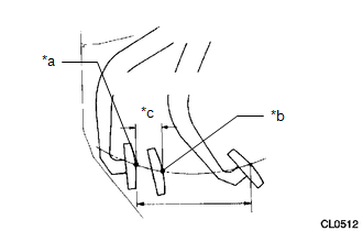
(f) Check the clutch release point. Text in Illustration
(1) Pull the parking brake lever and use wheel chocks to stabilize the vehicle. (2) Start the engine and run it at idle. (3) Without depressing the clutch pedal, slowly move the shift lever to R until the gears contact. (4) Gently depress the clutch pedal and measure the stroke distance from the point that the gear noise stops (release point) up to the full stroke end position. Standard distance: 25 mm (0.984 in.) or more If the result is not as specified, perform the following procedures.
|
|
 Removal
REMOVAL
PROCEDURE
1. REMOVE CLUTCH MASTER CYLINDER ASSEMBLY
(See page )
2. REMOVE TURN OVER SPRING SEAT COMPRESSION SPRING
(a) Remove the compression spring.
...
 Installation
INSTALLATION
PROCEDURE
1. INSTALL CLUTCH PEDAL NO.1 CUSHION
(a) Install the clutch pedal No. 1 cushion to the clutch pedal sub-assembly.
2. INSTALL CLUTCH PEDAL SHAFT COLLAR
(a) Apply MP grease t ...
Other materials:
Radio Broadcast cannot be Received or Poor Reception
PROCEDURE
1.
CHECK RADIO AND DISPLAY RECEIVER ASSEMBLY
(a) Check the radio automatic station search function.
(1) Check the radio automatic station search function by activating it.
Result
Result
Proceed to
Automatic station ...
Driver Side Power Window Auto Up / Down Function does not Operate with Power
Window Master Switch
DESCRIPTION
If the manual up/down function can be performed but the auto up/down function
cannot, then the fail-safe mode may be functioning.
If the power window initialization (See page
) has not been performed, the auto up/down function will not operate.
WIRING DIAGRAM
CAUTION / NOTICE ...
On-vehicle Inspection
ON-VEHICLE INSPECTION
PROCEDURE
1. INSPECT LOWER NO. 1 INSTRUMENT PANEL AIRBAG ASSEMBLY (for Vehicle not Involved
in Collision)
(a) Perform a diagnostic system check (See page
).
(b) With the lower No. 1 instrument panel airbag assembly ...
