Toyota Tacoma (2015-2018) Service Manual: Zero Point Calibration of Yaw Rate Sensor Undone (C1210,C1336)
DESCRIPTION
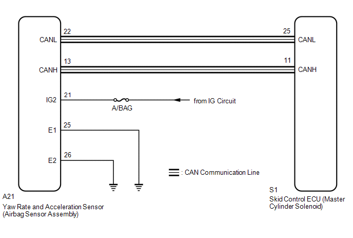
The skid control ECU (master cylinder solenoid) receives signals from the yaw rate and acceleration (airbag sensor assembly) via the CAN communication system.
The airbag sensor assembly has a built-in yaw rate and acceleration sensor and detects the vehicle's condition using 2 circuits (GL1, GL2).
If there is trouble in the bus lines between the yaw rate and acceleration sensor (airbag sensor assembly) and the CAN communication system, DTCs U0123 (yaw rate sensor communication trouble) and U0124 (acceleration sensor communication trouble) are stored.
These DTCs are also output when calibration has not been completed.
|
DTC Code |
DTC Detection Condition |
Trouble Area |
|---|---|---|
|
C1210 |
Zero point calibration of the yaw rate sensor is incomplete. |
|
|
C1336 |
Zero point calibration of the acceleration sensor is incomplete. |
WIRING DIAGRAM
CAUTION / NOTICE / HINT
NOTICE:
- When replacing the skid control ECU (master cylinder solenoid), perform
calibration (See page
.gif) ).
). - When replacing the yaw rate and acceleration sensor (airbag sensor assembly),
perform zero point calibration (See page
)
- Inspect the fuses for circuits related to this system before performing the following inspection procedure.
PROCEDURE
|
1. |
CHECK CAN COMMUNICATION SYSTEM |
(a) Check for DTCs (See page
).
|
Result |
Proceed to |
|---|---|
|
CAN DTC is not output |
A |
|
CAN DTC is output |
B |
| B | .gif) |
GO TO CAN COMMUNICATION SYSTEM (HOW TO PROCEED WITH TROUBLESHOOTING) |
|
.gif)
|
2. |
PERFORM ZERO POINT CALIBRATION OF YAW RATE AND ACCELERATION SENSOR |
(a) Perform zero point calibration of the yaw rate and acceleration sensor (See
page ).
|
|
3. |
PERFORM TEST MODE (SIGNAL CHECK) |
(a) Turn the ignition switch off.
(b) Perform the signal check in the Test Mode Procedure (See page
).
OK:
All test mode DTCs are cleared.
| OK | |
END |
|
|
4. |
CHECK AIRBAG SENSOR ASSEMBLY INSTALLATION |
(a) Turn the ignition switch off.
(b) Check that the yaw rate and acceleration sensor (airbag sensor assembly)
has been installed properly (See page
).
OK:
The sensor is tightened to the specified torque.
The sensor is not installed at an angle.
| NG | |
INSTALL AIRBAG SENSOR ASSEMBLY CORRECTLY |
|
|
5. |
READ VALUE USING TECHSTREAM (YAW RATE AND ACCELERATION SENSOR) |
(a) Turn the ignition switch off.
(b) Connect the Techstream to the DLC3.
(c) Turn the ignition switch to ON.
(d) Turn the Techstream on.
(e) Enter the following menus: Chassis / ABS/VSC/TRAC / Data List.
ABS/VSC/TRAC|
Tester Display |
Measurement Item/Range |
Normal Condition |
Diagnostic Note |
|---|---|---|---|
|
Deceleration Sensor |
Acceleration sensor/ Min.: -18.525 m/s2, Max.: 18.387 m/s2 |
- |
Changes continuously during acceleration/deceleration. |
|
Deceleration Sensor2 |
Acceleration sensor 2/ Min.: -18.525 m/s2, Max.: 18.387 m/s2 |
- |
Changes continuously during acceleration/deceleration. |
|
Yaw Rate Sensor |
Yaw rate sensor/ Min.: -128°/s, Max.: 127°/s |
0°/s: Vehicle stationary -128 to 0°/s: Right turn 0 to 127°/s: Left turn |
- |
(f) Check that the yaw rate and acceleration sensor output value is displayed on the Techstream.
OK:
The yaw rate and acceleration sensor output value is normal.
NOTICE:
The yaw rate and acceleration sensor (airbag sensor assembly) output value is
normal (See page
).
| OK | |
REPLACE MASTER CYLINDER SOLENOID |
| NG | |
REPLACE AIRBAG SENSOR ASSEMBLY |
 Control Module Communication Bus OFF (U0073,U0100,U0114,U0123,U0124,U0126)
DESCRIPTION
The skid control ECU (master cylinder solenoid) receives the signals from the
ECM, steering angle sensor (spiral cable with sensor sub-assembly), 4 wheel drive
control ECU*, and yaw r ...
 SM Solenoid Circuit (C1225-C1228,C1468,C1469,C146A,C146B)
DESCRIPTION
The solenoid goes on when signals are received from the skid control ECU (master
cylinder solenoid) and controls the pressure action on the wheel cylinders thus
controlling the brakin ...
Other materials:
Navigation Antenna
Components
COMPONENTS
ILLUSTRATION
Installation
INSTALLATION
PROCEDURE
1. INSTALL NAVIGATION ANTENNA ASSEMBLY
(a) Install the navigation antenna assembly with the 2 screws.
(b) Engage the 2 clamps.
2. INSTALL NO. 1 HEATER TO REGISTER DUCT
(See page )
3. INSTALL INSTRUMENT PANEL SUB ...
Sleep Operation Failure of Occupant Classification ECU (B1796)
DESCRIPTION
During sleep mode, the occupant detection ECU monitors the condition of each
sensor while the ignition switch is off. In this mode, if the occupant detection
ECU detects an internal malfunction, DTC B1796 is set.
DTC No.
DTC Detections Conditions
Tr ...
No Sound can be Heard from Speakers
PROCEDURE
1.
CHECK AUDIO SETTINGS
(a) In sound output setting mode, set volume, fader and balance to the initial
values and check that the sound is normal.
OK:
Audio system returns to normal.
HINT:
Sound quality adjustment measures vary according to the type ...
