Toyota Tacoma (2015-2018) Service Manual: Voice Recognition Microphone Disconnected (B1579)
DESCRIPTION
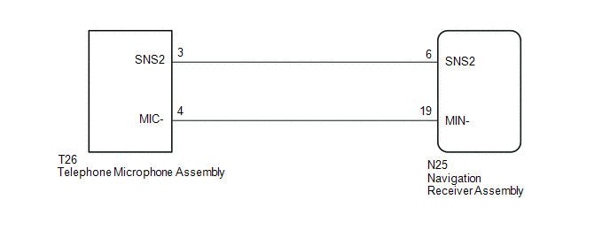
The navigation receiver assembly and telephone microphone assembly are connected to each other using the microphone connection detection signal lines.
This DTC is stored when the microphone connection detection signal is disconnected.
|
DTC Code |
DTC Detection Condition |
Trouble Area |
|---|---|---|
|
B1579 |
Telephone microphone signal is lost. |
|
WIRING DIAGRAM
PROCEDURE
|
1. |
INSPECT NAVIGATION RECEIVER ASSEMBLY |
(a) Remove the navigation receiver assembly with connector still connected.
|
(b) Measure the resistance according to the value(s) in the table below. Standard Resistance:
|
|
| NG | .gif) |
REPLACE NAVIGATION RECEIVER ASSEMBLY |
|
.gif)
|
2. |
CHECK HARNESS AND CONNECTOR (NAVIGATION RECEIVER ASSEMBLY - TELEPHONE MICROPHONE ASSEMBLY) |
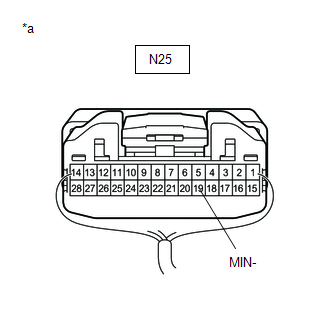
(a) Disconnect the N25 navigation receiver assembly connector.
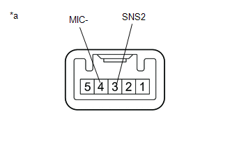
(b) Disconnect the T26 telephone microphone assembly.
(c) Measure the resistance according to the value(s) in the table below.
Standard Resistance:
|
Tester Connection |
Condition |
Specified Condition |
|---|---|---|
|
N25-6 (SNS2) - T26-3 (SNS2) |
Always |
Below 1 Ω |
|
N25-19 (MIN-) - T26-4 (MIC-) |
Always |
Below 1 Ω |
|
N25-6 (SNS2) - Body ground |
Always |
10 kΩ or higher |
|
N25-19 (MIN-) - Body ground |
Always |
10 kΩ or higher |
| NG | |
REPAIR OR REPLACE HARNESS OR CONNECTOR |
|
|
3. |
INSPECT TELEPHONE MICROPHONE ASSEMBLY |
(a) Remove the telephone microphone assembly (See page
.gif) ).
).
|
(b) Measure the resistance according to the value(s) in the table below. Standard Resistance:
|
|
| OK | |
REPLACE NAVIGATION RECEIVER ASSEMBLY |
| NG | |
REPLACE TELEPHONE MICROPHONE ASSEMBLY |
 Stereo Component Amplifier Disconnected (B15D3)
DESCRIPTION
The navigation receiver assembly and stereo component amplifier assembly are
connected by the AVC-LAN communication line.
When an AVC-LAN communication error occurs between the navigat ...
 Satellite Radio Broadcast cannot be Received
CAUTION / NOTICE / HINT
NOTICE:
Some satellite radio broadcasts require payment. A contract must be
made between a satellite radio company and the user. If the contract expires,
it w ...
Other materials:
How To Proceed With Troubleshooting
CAUTION / NOTICE / HINT
HINT:
Use the following procedure to troubleshoot the blind spot monitor system.
*: Use the Techstream.
PROCEDURE
1.
VEHICLE BROUGHT TO WORKSHOP
NEXT
...
System Description
SYSTEM DESCRIPTION
1. ENGINE IMMOBILISER SYSTEM DESCRIPTION
(a) The engine immobiliser system determines whether or not to enable starting
of the SFI system based on a comparison of the key ID code and the vehicle pre-registered
code. The engine immobiliser system compares the vehicle certific ...
Removal
REMOVAL
PROCEDURE
1. REMOVE FRONT SEAT ASSEMBLY (for Driver Side)
(See page )
2. REMOVE FRONT SEAT ASSEMBLY (for Front Passenger Side)
(See page )
3. REMOVE SEPARATE TYPE FRONT SEAT CUSHION COVER (for Driver Side)
(See page )
4. REMOVE SEPARATE TYPE FRONT SEAT CUSHION COVER (for Front Pas ...
