Toyota Tacoma (2015-2018) Service Manual: SM Solenoid Circuit (C1225-C1228,C1468,C1469,C146A,C146B)
DESCRIPTION
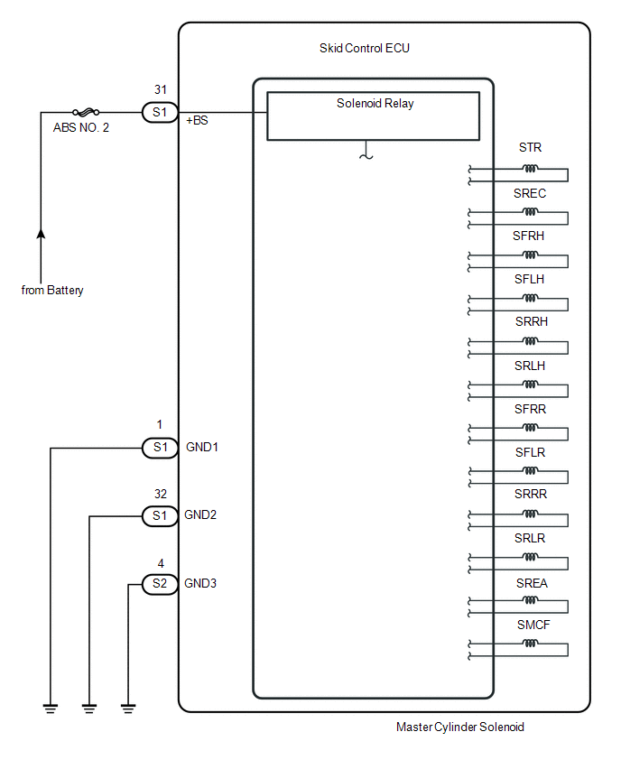
The solenoid goes on when signals are received from the skid control ECU (master cylinder solenoid) and controls the pressure action on the wheel cylinders thus controlling the braking force.
|
DTC No. |
DTC Detecting Conditions |
Trouble Areas |
|---|---|---|
|
C1225 |
Open or short in SMCR circuit continues for 0.05 seconds or more. |
|
|
C1226 |
Open or short in SREA circuit continues for 0.05 seconds or more. |
|
|
C1227 |
Open or short in SREC circuit continues for 0.05 seconds or more. |
|
|
C1228 |
Open or short in STR circuit continues for 0.05 seconds or more. |
|
|
C1468 |
Open or short in SFRH or SFRR circuit continues for 0.05 seconds or more. |
|
|
C1469 |
Open or short in SFLH or SFLR circuit continues for 0.05 seconds or more. |
|
|
C146A |
Open or short in SRRH or SRRR circuit continues for 0.05 seconds or more. |
|
|
C146B |
Open or short in SRLH or SRLR circuit continues for 0.05 seconds or more. |
|
WIRING DIAGRAM
PROCEDURE
|
1. |
RECONFIRM DTC |
HINT:
This DTCs are set when a problem is identified in the master cylinder solenoid.
The solenoid circuit is in the master cylinder solenoid.
Therefore, solenoid circuit inspection and solenoid unit inspection cannot be performed. Be sure to check if the DTCs are output before replacing the master cylinder solenoid.
(a) Clear the DTC (See page .gif) ).
).
(b) Check if the same DTCs are detected.
|
Result |
Proceed to |
|---|---|
|
DTC output |
A |
|
DTC not output |
B |
| A | .gif) |
REPLACE MASTER CYLINDER SOLENOID |
| B | |
END |
 Zero Point Calibration of Yaw Rate Sensor Undone (C1210,C1336)
DESCRIPTION
The skid control ECU (master cylinder solenoid) receives signals from the yaw
rate and acceleration (airbag sensor assembly) via the CAN communication system.
The airbag sensor assembl ...
 Acceleration Sensor Stuck Malfunction (C1232,C1243,C1245,C1279)
DESCRIPTION
The skid control ECU (master cylinder solenoid) receives signals from the yaw
rate and acceleration (airbag sensor assembly) via the CAN communication system.
The airbag sensor assembl ...
Other materials:
Communication Malfunction between ECUs Connected by LIN (B2785)
DESCRIPTION
The certification ECU (smart key ECU assembly) monitors communication between
all the ECUs connected to the certification bus lines. When the certification ECU
(smart key ECU assembly) detects errors in communication with all the ECUs connected
to the certification bus lines at a ...
Vehicle Speed Sensor Circuit (C1AA3)
DESCRIPTION
The forward recognition camera receives vehicle speed signals from the skid control
ECU. If the skid control ECU receives a vehicle speed sensor malfunction signal,
it informs the forward recognition camera via CAN communication, and DTC C1AA3 is
stored.
DTC No.
...
Wireless Charger Power Source Circuit
DESCRIPTION
This is the power source circuit to operate the mobile wireless charger cradle
assembly.
WIRING DIAGRAM
CAUTION / NOTICE / HINT
NOTICE:
Inspect the fuses for circuits related to this system before performing the following
inspection procedure.
PROCEDURE
1.
...
