Toyota Tacoma (2015-2018) Service Manual: Washer Level Warning Switch
Components
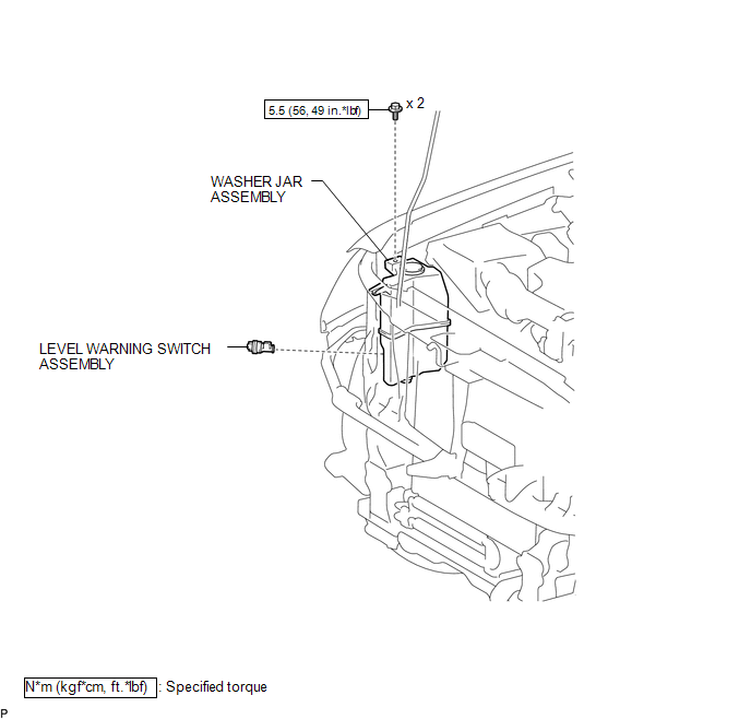
COMPONENTS
ILLUSTRATION
Inspection
INSPECTION
PROCEDURE
1. INSPECT LEVEL WARNING SWITCH ASSEMBLY
HINT:
This check should be performed with the windshield washer motor and pump assembly installed on the washer jar.
(a) Fill the washer jar with washer fluid.
|
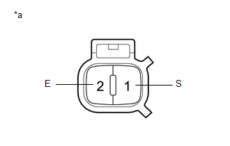
(b) Measure the resistance according to the value(s) in the table below. Standard Resistance:
HINT: *: The level warning switch assembly begins operating when the fluid volume is 600 to 800 cc (36.6 to 48.8 cu.in.) depending on the vehicle condition. Text in Illustration
If the result is not as specified, replace the level warning switch assembly. |
|
Installation
INSTALLATION
PROCEDURE
1. INSTALL LEVEL WARNING SWITCH ASSEMBLY
|
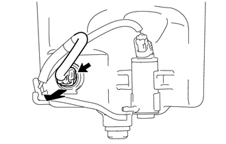
(a) Install the level warning switch assembly. |
|
(b) Connect the connector.
(c) Connect the washer hose to the windshield washer motor and pump assembly.
2. INSTALL WASHER JAR ASSEMBLY
.gif)
3. ADD WASHER FLUID
4. INSTALL HEADLIGHT ASSEMBLY RH
HINT:
Use the same procedure as for the LH side. (See page
)
Removal
REMOVAL
PROCEDURE
1. REMOVE HEADLIGHT ASSEMBLY RH
HINT:
Use the same procedure as for the LH side. (See page
.gif) )
)
2. SEPARATE WASHER JAR ASSEMBLY
3. DRAIN WINDSHIELD WASHER FLUID
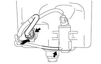
4. REMOVE LEVEL WARNING SWITCH ASSEMBLY
|
(a) Disconnect the connector. |
|
(b) Remove the level warning switch assembly as shown in the illustration.
 Front Wiper Rubber
Components
COMPONENTS
ILLUSTRATION
Installation
INSTALLATION
PROCEDURE
1. INSTALL FRONT WIPER RUBBER
(a) Install the 2 wiper rubber backing plates to the front wiper rubber.
...
 Washer Motor
Components
COMPONENTS
ILLUSTRATION
On-vehicle Inspection
ON-VEHICLE INSPECTION
PROCEDURE
1. INSPECT WINDSHIELD WASHER MOTOR AND PUMP ASSEMBLY
HINT:
This check should be performed with th ...
Other materials:
Image from Camera for Rear View Monitor is Abnormal
DESCRIPTION
The display signal of the rear television camera assembly is transmitted to the
radio and display receiver assembly*1 or navigation receiver assembly*2.
*1: w/o Navigation System
*2: w/ Navigation System
WIRING DIAGRAM
PROCEDURE
1.
CONFIRM ...
Diagnosis System
DIAGNOSIS SYSTEM
1. DESCRIPTION
The ECU stores trouble codes when malfunctions occur.
The diagnostic system allows for reading of the trouble codes from the DLC3.
Use the Techstream to help diagnose and repair the problem.
2. CHECK DLC3
(a) Check the DLC3 (See page ).
3. INSPECT BATTERY VOLT ...
Open or Short in Front Speed Sensor RH Circuit (C1405,C1406)
DESCRIPTION
Refer to DTCs C1401 and C1402 (See page ).
DTC Code
DTC Detection Condition
Trouble Area
C1405
C1406
Either condition is met:
An open in the speed sensor signal circuit continues for 0.5
seconds or mor ...
