Toyota Tacoma (2015-2018) Service Manual: Washer Motor
Components
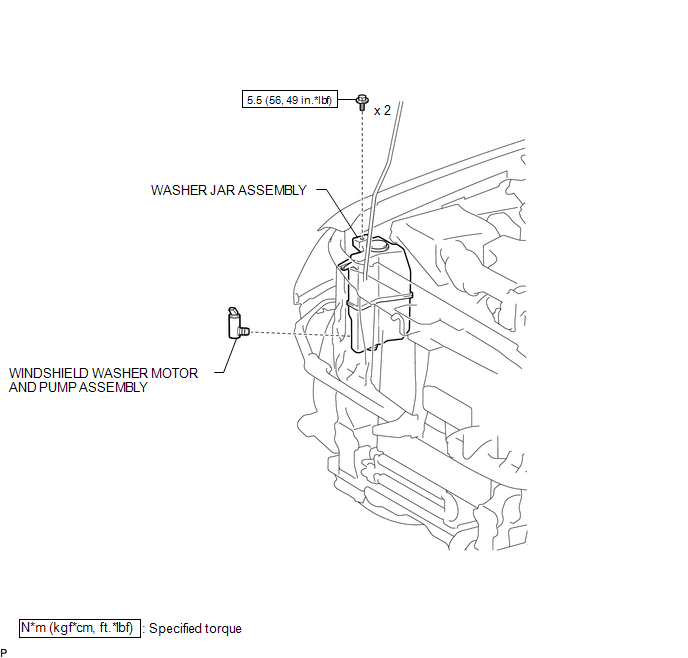
COMPONENTS
ILLUSTRATION
On-vehicle Inspection
ON-VEHICLE INSPECTION
PROCEDURE
1. INSPECT WINDSHIELD WASHER MOTOR AND PUMP ASSEMBLY
HINT:
This check should be performed with the windshield washer motor and pump assembly installed to the windshield washer jar assembly.
|
(a) With the windshield washer motor and pump assembly installed to the washer jar, pour windshield washer fluid into the washer jar. Text in Illustration
|
|
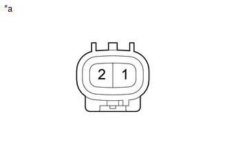
(b) Check that the windshield washer fluid is pumped when battery voltage is applied to the terminals.
:
|
Condition |
Specified Condition |
|---|---|
|
Battery positive (+) → Terminal 1 Battery negative (-) → Terminal 2 |
Washer fluid is pumped |
If the result is not as specified, replace the windshield washer motor and pump assembly.
Removal
REMOVAL
PROCEDURE
1. REMOVE HEADLIGHT ASSEMBLY RH
HINT:
Use the same procedure as for the LH side (See page
.gif) ).
).
2. SEPARATE WASHER JAR ASSEMBLY
|
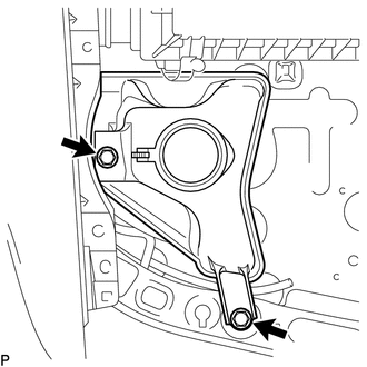
(a) Remove the 2 bolts to separate the washer jar assembly from the vehicle body. |
|
3. DRAIN WINDSHIELD WASHER FLUID
|
(a) Disconnect the washer hose from the windshield washer motor and pump assembly, and drain the windshield washer fluid. HINT: Use a container to collect the washer fluid. |
|
4. REMOVE WINDSHIELD WASHER MOTOR AND PUMP ASSEMBLY
|
(a) Disconnect the connector. |
|
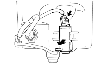
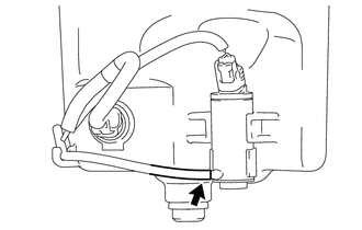
(b) Remove the windshield washer motor and pump assembly as shown in the illustration.
Installation
INSTALLATION
PROCEDURE
1. INSTALL WINDSHIELD WASHER MOTOR AND PUMP ASSEMBLY
|
(a) Install the windshield washer motor and pump assembly. |
|
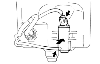
(b) Connect the washer hose.
(c) Connect the connector.
2. INSTALL WASHER JAR ASSEMBLY
|
(a) Install the windshield washer jar assembly with the 2 bolts in the order shown in the illustration. Torque: 5.5 N·m {56 kgf·cm, 49 in·lbf} |
|

3. ADD WASHER FLUID
(a) Add washer fluid to the washer jar assembly.
4. INSTALL HEADLIGHT ASSEMBLY RH
HINT:
Use the same procedure as for the LH side. (See page
.gif) )
)
 Washer Level Warning Switch
Components
COMPONENTS
ILLUSTRATION
Inspection
INSPECTION
PROCEDURE
1. INSPECT LEVEL WARNING SWITCH ASSEMBLY
HINT:
This check should be performed with the windshield washer motor and pump ...
 Washer Nozzle
Components
COMPONENTS
ILLUSTRATION
On-vehicle Inspection
ON-VEHICLE INSPECTION
PROCEDURE
1. INSPECT WASHER NOZZLE SUB-ASSEMBLY
(a) Operate the washer nozzle sub-assembly and check the pos ...
Other materials:
How To Proceed With Troubleshooting
CAUTION / NOTICE / HINT
HINT:
Use the following procedure to troubleshoot the air conditioning system.
*: Use the Techstream.
PROCEDURE
1.
VEHICLE BROUGHT TO WORKSHOP
NEXT
...
Cellular Phone Inspection
PROCEDURE
1.
CHECK USAGE CONDITION
(a) Check that the vehicle and cellular phone meet the following conditions:
NOTICE:
If changing cellular phone settings, updating software, etc. is necessary, make
sure to obtain the permission of the customer before performin ...
SM Solenoid Circuit (C1225-C1228,C1468,C1469,C146A,C146B)
DESCRIPTION
The solenoid goes on when signals are received from the skid control ECU (master
cylinder solenoid) and controls the pressure action on the wheel cylinders thus
controlling the braking force.
DTC No.
DTC Detecting Conditions
Trouble Areas
...
