Toyota Tacoma (2015-2018) Service Manual: Noise Filter(for 2tr-fe)
Components
COMPONENTS
ILLUSTRATION
.png)
Removal
REMOVAL
PROCEDURE
1. DISCONNECT CABLE FROM NEGATIVE BATTERY TERMINAL
2. REMOVE AIR CLEANER ASSEMBLY
(See page .gif) )
)
3. REMOVE RADIO SETTING CONDENSER
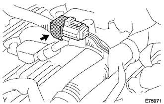
(a) Disconnect the connector.
(b) Remove the tape and the radio setting condenser.
Installation
INSTALLATION
PROCEDURE
1. INSTALL RADIO SETTING CONDENSER
.png)
(a) Connect the connector.
(b) Wind new vinyl tape around the hose and install the radio setting condenser.
2. INSTALL AIR CLEANER ASSEMBLY
(See page .gif) )
)
3. CONNECT CABLE TO NEGATIVE BATTERY TERMINAL
Torque:
5.4 N·m {55 kgf·cm, 48 in·lbf}
 Noise Filter(for 2gr-fks)
Components
COMPONENTS
ILLUSTRATION
Removal
REMOVAL
PROCEDURE
1. DISCONNECT CABLE FROM NEGATIVE BATTERY TERMINAL
2. REMOVE V-BANK COVER
(See page )
3. REMOVE AIR CLEANER ASSEMBLY
(See ...
 Radio Antenna
Components
COMPONENTS
ILLUSTRATION
Removal
REMOVAL
PROCEDURE
1. REMOVE ROOF HEADLINING ASSEMBLY (for Double Cab)
(See page )
2. REMOVE ROOF HEADLINING ASSEMBLY (for Access Cab)
(See p ...
Other materials:
Disassembly
DISASSEMBLY
CAUTION / NOTICE / HINT
HINT:
Use the same procedure for both the LH and RH sides.
The procedure described below is for the LH side.
PROCEDURE
1. REMOVE NO. 1 HEADLIGHT BULB
(a) Turn the No. 1 headlight bulb in the direction indicated by the arrow
i ...
Transmitter Battery(w/ Smart Key System)
Replacement
REPLACEMENT
CAUTION / NOTICE / HINT
NOTICE:
Take extra care when handling these precision electronic components.
PROCEDURE
1. REMOVE TRANSMITTER BATTERY
(a) Push the release hook knob and extract the mechanical key as shown
in the illustration.
Text in Illustra ...
Speed Sensor
Components
COMPONENTS
ILLUSTRATION
Removal
REMOVAL
PROCEDURE
1. REMOVE TRANSMISSION REVOLUTION SENSOR (NT)
(a) Disconnect the transmission revolution sensor (NT) connector.
(b) Remove the bolt and transmission revolution sensor (NT). ...
