Toyota Tacoma (2015-2018) Service Manual: Front Wiper Rubber
Components
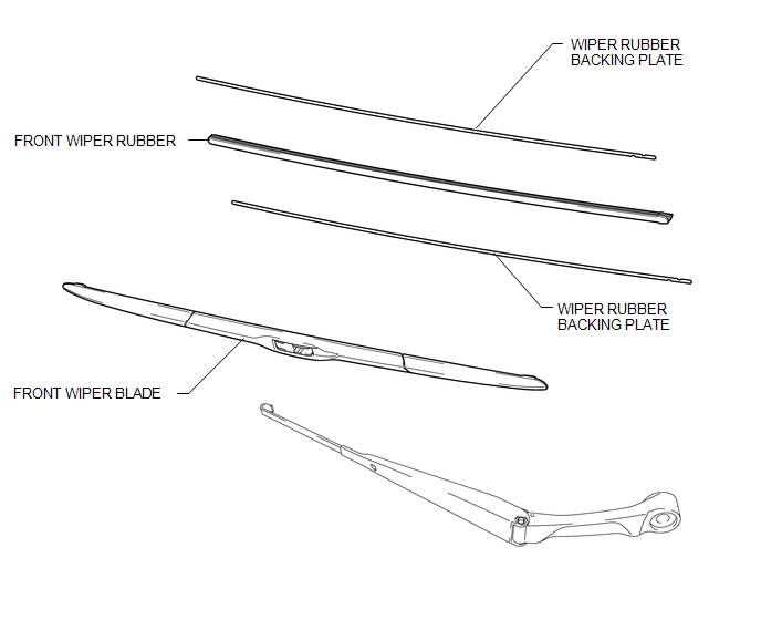
COMPONENTS
ILLUSTRATION
Installation
INSTALLATION
PROCEDURE
1. INSTALL FRONT WIPER RUBBER
|
(a) Install the 2 wiper rubber backing plates to the front wiper rubber. NOTICE:
|
|
|
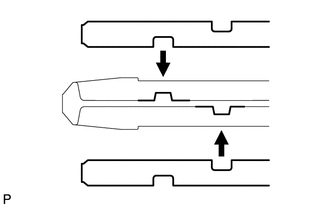
(b) Install the front wiper rubber together with the 2 front wiper rubber backing plates to the front wiper blade. NOTICE: Push the front wiper blade into the grooves of the wiper rubber to engage them completely. HINT: Install the wiper rubber LH so that the head part (large side) of the wiper rubber faces the arm axis side. |
|
2. INSTALL FRONT WIPER BLADE
|
(a) Install the front wiper blade to the front wiper arm as shown in the illustration. Text in Illustration
|
|
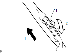
(b) Install the holder of the front wiper blade as shown in the illustration.
Removal
REMOVAL
CAUTION / NOTICE / HINT
NOTICE:
Make sure to hold the front wiper arm while lifting it as lifting the front wiper arm by the front wiper blade may damage or deform the front wiper blade
HINT:
- The following procedure is for the LH side.
- Use the same procedure for the RH side and LH side.
PROCEDURE
1. REMOVE FRONT WIPER BLADE
|
(a) Remove the holder of the front wiper blade as shown in the illustration. Text in Illustration
|
|
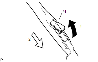
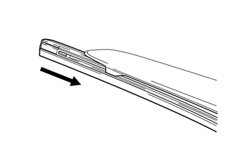
(b) Remove the front wiper blade from the front wiper arm as shown in the illustration.
NOTICE:
Do not lower the front wiper arm with the front wiper blade removed. The arm tip may damage the windshield surface.
2. REMOVE FRONT WIPER RUBBER
|
(a) Remove the front wiper rubber with wiper rubber backing plates from the front wiper blade. |
|
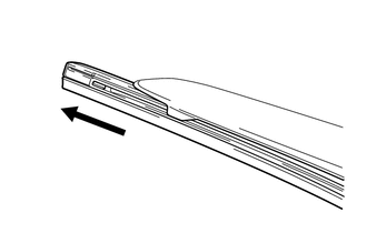
(b) Remove the 2 wiper rubber backing plates from the front wiper rubber.
 Removal
REMOVAL
PROCEDURE
1. REMOVE FRONT WIPER ARM HEAD CAP
(a) Using a screwdriver with its tip wrapped in protective tape, disengage
the 3 claws to remove the front wiper arm head cap.
...
 Washer Level Warning Switch
Components
COMPONENTS
ILLUSTRATION
Inspection
INSPECTION
PROCEDURE
1. INSPECT LEVEL WARNING SWITCH ASSEMBLY
HINT:
This check should be performed with the windshield washer motor and pump ...
Other materials:
Removal
REMOVAL
CAUTION / NOTICE / HINT
HINT:
Use the same procedure for the LH side and RH side.
The following procedure listed is for the LH side.
PROCEDURE
1. REMOVE FRONT WHEEL
2. DRAIN BRAKE FLUID
NOTICE:
Immediately wash off any brake fluid that comes into contact with any pa ...
Problem Symptoms Table
PROBLEM SYMPTOMS TABLE
HINT:
Use the table below to help determine the cause of problem symptoms.
If multiple suspected areas are listed, the potential causes of the symptoms
are listed in order of probability in the "Suspected Area" column of the
table. Check each sy ...
Installation
INSTALLATION
PROCEDURE
1. INSTALL INSTRUMENT PANEL PASSENGER AIRBAG ASSEMBLY WITHOUT DOOR
(a) Engage the 3 hooks (B).
Text in Illustration
*a
Hooks (A)
*b
Hooks (B)
...
