Toyota Tacoma (2015-2018) Service Manual: VSC OFF Switch Circuit
DESCRIPTION
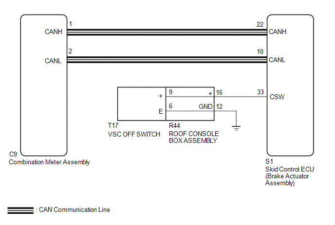
The skid control ECU assembly is connected to the combination meter assembly via CAN communication.
Pressing the VSC OFF switch turns off TRAC operation, and pressing and holding this switch turns off TRAC and VSC operation.
If TRAC and VSC operations are turned off, the TRAC OFF indicator and the VSC OFF indicator lights come on.
for 4WD:
When the 4WD control switch (transfer position switch) set to L4, VSC is prohibited and the VSC OFF indicator light turns on.
w/ Rear Differential Lock:
When the rear differential is locked, VSC is prohibited, the VSC OFF indicator turns on and the TRAC OFF message is displayed.
WIRING DIAGRAM
CAUTION / NOTICE / HINT
NOTICE:
- When replacing the skid control ECU (brake actuator assembly), perform
zero point calibration and store system information (See page
.gif) ).
).
- for 4WD:
As there may be malfunctions in the touch select 2-4 and high-low system related to when the transfer operates in L4, check the touch select 2-4 and high-low system first (See page
).
PROCEDURE
|
1. |
CHECK CAN COMMUNICATION SYSTEM |
(a) Check if CAN communication system DTCs are output (See page
).
|
Result |
Proceed to |
|---|---|
|
DTC is not output |
A |
|
DTC is output |
B |
| B | .gif) |
CHECK CAN COMMUNICATION SYSTEM |
|
.gif)
|
2. |
CHECK IF SKID CONTROL ECU ASSEMBLY CONNECTOR IS SECURELY CONNECTED |
(a) Check if the skid control ECU assembly (brake actuator assembly) connector is securely connected.
OK:
The connector is securely connected.
Result|
Result |
Proceed to |
|---|---|
|
OK (w/ Rear Differential Lock) |
A |
|
OK (w/o Rear Differential Lock) |
B |
|
NG |
C |
| B | |
GO TO STEP 4 |
| C | |
CONNECT CONNECTOR TO SKID CONTROL ECU ASSEMBLY CORRECTLY |
|
|
3. |
CHECK FOR DIFFERENTIAL SYSTEM |
(a) Connect the Techstream to the DLC3.
(b) Turn the ignition switch to ON.
(c) Turn the Techstream on.
(d) Enter the following menus: Powertrain / Four Wheel Drive / Trouble Codes.
(e) Check for DTCs.
Result|
Result |
Proceed to |
|---|---|
|
DTCs are not output |
A |
|
DTCs are output |
B |
| B | |
GO TO DIFFERENTIAL SYSTEM (DIAGNOSTIC TROUBLE CODE CHART) |
|
|
4. |
READ VALUE USING TECHSTREAM (TRAC/VSC OFF MODE) |
(a) Reconnect the S1 skid control ECU (brake actuator assembly) connector.
(b) Connect the Techstream to the DLC3.
(c) Turn the ignition switch to ON.
(d) Select the Data List on the Techstream (See page
).
|
Tester Display |
Measurement Item |
Range |
Normal Condition |
Diagnostic Note |
|---|---|---|---|---|
|
TRC/VSC Off Mode |
TRAC/VSC off mode |
Normal, TRAC OFF, Unknown or VSC OFF |
Normal: Normal mode TRAC OFF: TRAC off mode VSC OFF: VSC off mode |
Unknown: Unspecified |
(e) Check that the indicator light and mode condition on the Techstream change according to VSC OFF switch operation.
Standard:
|
Switch Operation |
Mode Condition Display |
TRAC OFF Indicator Light |
VSC OFF Indicator Light |
|---|---|---|---|
|
Not pressed |
Normal |
Not displayed |
Does not come on |
|
Pressing the VSC OFF switch |
TRAC OFF |
Comes on |
Does not come on |
|
Pressing and holding the VSC OFF switch |
VSC OFF |
Comes on |
Comes on |
|
Result |
Proceed to |
|---|---|
|
Indicator light and mode condition display do not change. |
A |
|
Mode condition display is normal, but indicator light does not change. |
B |
|
Indicator light and mode condition display are normal. |
C |
| B | |
INSPECT METER / GAUGE SYSTEM |
| C | |
USE SIMULATION METHOD TO CHECK |
|
|
5. |
PERFORM ACTIVE TEST USING TECHSTREAM (TRC (TRAC) OFF INDICATOR LIGHT AND VSC OFF INDICATOR LIGHT) |
(a) Select the Active Test on the Techstream (See page
).
|
Tester Display |
Measurement Item |
Control Range |
Diagnostic Note |
|---|---|---|---|
|
TRC(TRAC) OFF Indicator Light |
TRAC OFF indicator light |
Indicator light ON/OFF |
Observe combination meter assembly Vehicle condition: Vehicle stopped |
|
VSC OFF Indicator Light |
VSC OFF indicator light |
Indicator light ON/OFF |
Observe combination meter assembly Vehicle condition: Vehicle stopped |
(b) Check the TRAC OFF indicator light and VSC OFF indicator light on the combination meter assembly turn ON or OFF in accordance with the Techstream operation.
OK:
The TRAC OFF indicator light and VSC OFF indicator light turn ON or OFF in accordance with the Techstream operation.
| NG | |
GO TO STEP 9 |
|
|
6. |
INSPECT VSC OFF SWITCH |
(a) Turn the ignition switch off.
(b) Remove the VSC OFF switch (See page ).
(c) Inspect the VSC OFF switch (See page ).
OK:
The VSC OFF switch operates normally.
| NG | |
REPLACE VSC OFF SWITCH |
|
|
7. |
INSPECT ROOF CONSOLE BOX ASSEMBLY |
(a) Remove the roof console box assembly.
- for Double Cab:
- for Access Cab:
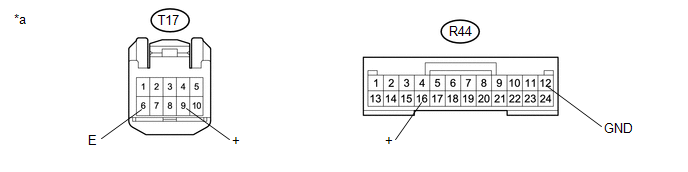 Text in Illustration
|
*a |
Component without harness connected (Roof Console Box Assembly) |
- |
- |
(b) Measure the resistance according the value(s) in the table below.
Standard Resistance:
|
Tester Connection |
Condition |
Specified Condition |
|---|---|---|
|
R44-16 (+) - T17-9 (+) |
Always |
Below 1 Ω |
|
R44-12 (GND) - T17-6 (E) |
Always |
Below 1 Ω |
|
Result |
Proceed to |
|---|---|
|
OK |
A |
|
NG (for Double Cab) |
B |
|
NG (for Access Cab) |
C |
| B | |
REPLACE ROOF CONSOLE BOX ASSEMBLY |
| C | |
REPLACE ROOF CONSOLE BOX ASSEMBLY |
|
|
8. |
CHECK HARNESS AND CONNECTOR (BRAKE ACTUATOR ASSEMBLY - VSC OFF SWITCH) |
(a) Disconnect the S1 skid control ECU (brake actuator assembly) connector.
(b) Measure the resistance according to the value(s) in the table below.
Standard Resistance:
|
Tester Connection |
Condition |
Specified Condition |
|---|---|---|
|
S1-33 (CSW) - R44-16 (+) |
Always |
Below 1 Ω |
|
S1-33 (CSW) or R44-16 (+) - Body groundd |
Always |
10 kΩ or higher |
|
R44-12 (GND) - Body ground |
Always |
Below 1 Ω |
| OK | |
REPLACE BRAKE ACTUATOR ASSEMBLY |
| NG | |
REPAIR OR REPLACE HARNESS OR CONNECTOR |
|
9. |
INSPECT COMBINATION METER ASSEMBLY |
(a) Turn the ignition switch off.
(b) Perform the Active Test of the combination meter assembly using the Techstream
(See page ).
(c) Check the combination meter assembly.
OK:
The TRAC OFF indicator light turns on or off in accordance with the Techstream.
| OK | |
REPLACE BRAKE ACTUATOR ASSEMBLY |
| NG | |
INSPECT METER / GAUGE SYSTEM |
 TS and CG Terminal Circuit
DESCRIPTION
In Test Mode (signal check), a malfunction in the speed sensor that cannot be
detected when the vehicle is stopped can be detected while driving.
Sensor check mode can be entered by co ...
 Vsc Off Switch
Components
COMPONENTS
ILLUSTRATION
Inspection
INSPECTION
PROCEDURE
1. INSPECT VSC OFF SWITCH
(a) Check the resistance.
(1) Measure the resistance according to the value(s) in ...
Other materials:
Stereo Component Amplifier Malfunction (B15A3)
DESCRIPTION
This DTC is stored when a malfunction occurs in the stereo component amplifier
assembly.
DTC No.
DTC Detection Condition
Trouble Area
B15A3
When one of the conditions below is met:
Internal power supply malfun ...
Security Horn Assembly
Components
COMPONENTS
ILLUSTRATION
Inspection
INSPECTION
PROCEDURE
1. INSPECT SECURITY HORN ASSEMBLY
(a) Check the operation.
(1) Apply battery voltage and check operation of the security horn assembly.
OK:
Measurement Condition
Spe ...
Removal
REMOVAL
CAUTION / NOTICE / HINT
HINT:
Use the same procedure for both the LH and RH sides.
The procedure described below is for the LH side.
PROCEDURE
1. REMOVE NO. 1 FRONT WHEEL OPENING EXTENSION PAD (w/ Front Spoiler)
2. SEPARATE FRONT FENDER LINER
(a) Remov ...
