Toyota Tacoma (2015-2018) Service Manual: Side Airbag Sensor LH Circuit Malfunction (B1625/22)
DESCRIPTION
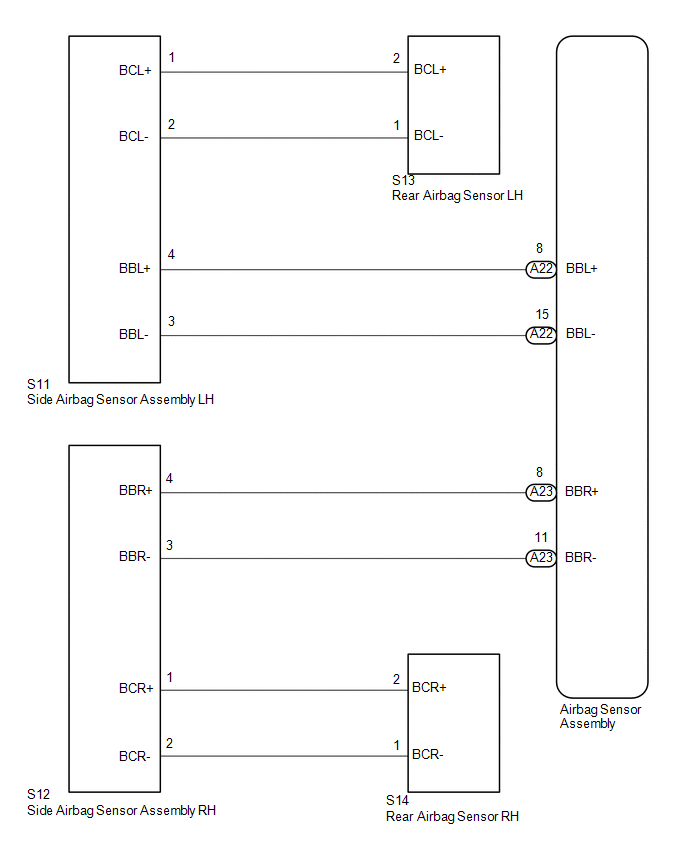
The side airbag sensor assembly LH consists of parts such as the safing sensor, the diagnostic circuit and the lateral deceleration sensor.
When the airbag sensor assembly receives signals from the lateral deceleration sensor, it determines whether or not the SRS should be activated.
DTC B1625/22 is set when a malfunction is detected in the side airbag sensor assembly LH and rear airbag sensor LH circuit.
|
DTC No. |
DTC Detecting Conditions |
Trouble Areas |
|---|---|---|
|
B1625/22 |
|
|
WIRING DIAGRAM
CAUTION / NOTICE / HINT
NOTICE:
After turning the ignition switch off, waiting time may be required before disconnecting
the cable from the negative (-) battery terminal. Therefore, make sure to read the
disconnecting the cable from the negative (-) battery terminal notices before proceeding
with work (See page .gif) ).
).
PROCEDURE
|
1. |
CHECK CONNECTION OF CONNECTORS |
(a) Turn the ignition switch off.
(b) Disconnect the negative (-) terminal cable from the battery, and wait for at least 90 seconds.
(c) Check that the connectors are properly connected to the airbag sensor assembly and the side airbag sensor assembly LH.
OK:
The connectors are properly connected.
| NG | .gif) |
CONNECT CONNECTORS |
|
.gif)
|
2. |
CHECK CONNECTORS |
(a) Check that the connectors (on the airbag sensor assembly side and side airbag
sensor assembly LH side) are not damaged (See page
).
OK:
The connectors are not deformed or damaged.
| NG | |
REPLACE WIRE HARNESS |
|
|
3. |
CHECK NO. 2 FLOOR WIRE (FOR OPEN) |
|
(a) Disconnect the connectors from the airbag sensor assembly and the side airbag sensor assembly LH. |
|
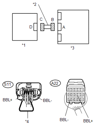
(b) Using service wire, connect S11-4 (BBL+) and S11-3 (BBL-) of connector C.
(c) Measure the resistance according to the value(s) in the table below.
Standard Resistance:
|
Tester Connection |
Condition |
Specified Condition |
|---|---|---|
|
A22-8 (BBL+) - A22-15 (BBL-) |
Always |
Below 1 Ω |
|
*1 |
Side Airbag Sensor Assembly LH |
|
*2 |
No. 2 Floor Wire |
|
*3 |
Airbag Sensor Assembly |
|
*4 |
Service Wire |
| NG | |
REPLACE NO. 2 FLOOR WIRE |
|
|
4. |
CHECK NO. 2 FLOOR WIRE (FOR SHORT) |
|
(a) Disconnect the service wire from connector C. |
|
(b) Measure the resistance according to the value(s) in the table below.
Standard Resistance:
|
Tester Connection |
Condition |
Specified Condition |
|---|---|---|
|
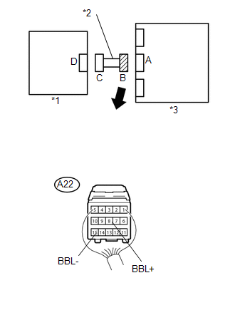
A22-8 (BBL+) - A22-15 (BBL-) |
Always |
1 MΩ or Higher |
|
*1 |
Side Airbag Sensor Assembly LH |
|
*2 |
No. 2 Floor Wire |
|
*3 |
Airbag Sensor Assembly |
| NG | |
REPLACE NO. 2 FLOOR WIRE |
|
|
5. |
CHECK NO. 2 FLOOR WIRE (TO B+) |
|
(a) Connect the negative (-) terminal cable to the battery, and wait for at least 2 seconds. |
|
(b) Turn the ignition switch to ON.
(c) Measure the voltage according to the value(s) in the table below.
Standard Voltage:
|
Tester Connection |
Switch Condition |
Specified Condition |
|---|---|---|
|
A22-8 (BBL+) - Body ground |
Ignition switch ON |
Below 1 V |
|
A22-15 (BBL-) - Body ground |
Ignition switch ON |
Below 1 V |
|
*1 |
Side Airbag Sensor Assembly LH |
|
*2 |
No. 2 Floor Wire |
|
*3 |
Airbag Sensor Assembly |
| NG | |
REPLACE NO. 2 FLOOR WIRE |
|
|
6. |
CHECK NO. 2 FLOOR WIRE (TO GROUND) |
|
(a) Turn the ignition switch off. |
|
(b) Disconnect the negative (-) terminal cable from the battery, and wait for at least 90 seconds.
(c) Measure the resistance according to the value(s) in the table below.
Standard Resistance:
|
Tester Connection |
Condition |
Specified Condition |
|---|---|---|
|
A22-8 (BBL+) - Body ground |
Always |
1 MΩ or Higher |
|
A22-15 (BBL-) - Body ground |
Always |
1 MΩ or Higher |
|
*1 |
Side Airbag Sensor Assembly LH |
|
*2 |
No. 2 Floor Wire |
|
*3 |
Airbag Sensor Assembly |
| NG | |
REPLACE NO. 2 FLOOR WIRE |
|
|
7. |
CHECK SIDE AIRBAG SENSOR ASSEMBLY LH |
(a) Connect the connectors to the airbag sensor assembly.
(b) Interchange the side airbag sensor assembly RH with the side airbag sensor assembly LH and connect the connectors to them.
(c) Connect the negative (-) terminal cable to the battery, and wait for at least 2 seconds.
(d) Turn the ignition switch to ON, and wait for at least 60 seconds.
(e) Clear the DTCs stored in the memory (See page
).
(f) Turn the ignition switch off.
(g) Turn the ignition switch to ON, and wait for at least 60 seconds.
(h) Check for DTCs (See page ).
|
Result |
Proceed to |
|---|---|
|
DTC B1625/22 is output. |
A |
|
DTC B1620/21 is output. |
B |
|
Neither DTC B1620/21 nor B1625/22 is output. |
C |
| B | |
REPLACE REAR AIRBAG SENSOR LH |
| C | |
USE SIMULATION METHOD TO CHECK |
|
|
8. |
CHECK CONNECTION OF CONNECTORS |
(a) Turn the ignition switch off.
(b) Disconnect the negative (-) terminal cable from the battery, and wait for at least 90 seconds.
(c) Check that the connectors are properly connected to the rear airbag sensor LH.
OK:
The connectors are properly connected.
| NG | |
CONNECT CONNECTORS |
|
|
9. |
CHECK CONNECTORS |
(a) Check that the connectors (on the side airbag sensor assembly LH side and
rear airbag sensor LH side) are not damaged (See page
).
OK:
The connectors are not deformed or damaged.
| NG | |
REPLACE WIRE HARNESS |
|
|
10. |
CHECK NO. 2 FLOOR WIRE (FOR OPEN) |
|
(a) Disconnect the connectors from the side airbag sensor assembly LH and the rear airbag sensor LH. |
|
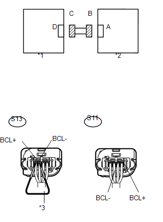
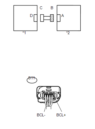
(b) Using service wire, connect S13-1 (BCL-) and S13-2 (BCL+) of connector C.
(c) Measure the resistance according to the value(s) in the table below.
Standard Resistance:
|
Tester Connection |
Condition |
Specified Condition |
|---|---|---|
|
S11-1 (BCL+) - S11-2 (BCL-) |
Always |
Below 1 Ω |
|
*1 |
Rear Airbag Sensor LH |
|
*2 |
Side Airbag Sensor Assembly LH |
|
*3 |
Service Wire |
| NG | |
REPLACE NO. 2 FLOOR WIRE |
|
|
11. |
CHECK NO. 2 FLOOR WIRE (FOR SHORT) |
|
(a) Disconnect the service wire from connector C. |
|
(b) Measure the resistance according to the value(s) in the table below.
Standard Resistance:
|
Tester Connection |
Condition |
Specified Condition |
|---|---|---|
|
S11-1 (BCL+) - S11-2 (BCL-) |
Always |
1 MΩ or Higher |
|
*1 |
Rear Airbag Sensor LH |
|
*2 |
Side Airbag Sensor Assembly LH |
| NG | |
REPLACE NO. 2 FLOOR WIRE |
|
|
12. |
CHECK NO. 2 FLOOR WIRE (TO B+) |
|
(a) Connect the negative (-) terminal cable to the battery, and wait for at least 2 seconds. |
|
(b) Turn the ignition switch to ON.
(c) Measure the voltage according to the value(s) in the table below.
Standard Voltage:
|
Tester Connection |
Switch Condition |
Specified Condition |
|---|---|---|
|
S11-1 (BCL+) - Body ground |
Ignition switch ON |
Below 1 V |
|
S11-2 (BCL-) - Body ground |
Ignition switch ON |
Below 1 V |
|
*1 |
Rear Airbag Sensor LH |
|
*2 |
Side Airbag Sensor Assembly LH |
| NG | |
REPLACE NO. 2 FLOOR WIRE |
|
|
13. |
CHECK NO. 2 FLOOR WIRE (TO GROUND) |
|
(a) Turn the ignition switch off. |
|
(b) Disconnect the negative (-) terminal cable from the battery, and wait for at least 90 seconds.
(c) Measure the resistance according to the value(s) in the table below.
Standard Resistance:
|
Tester Connection |
Condition |
Specified Condition |
|---|---|---|
|
S11-1 (BCL+) - Body ground |
Always |
1 MΩ or Higher |
|
S11-2 (BCL-) - Body ground |
Always |
1 MΩ or Higher |
|
*1 |
Rear Airbag Sensor LH |
|
*2 |
Side Airbag Sensor Assembly LH |
| NG | |
REPLACE NO. 2 FLOOR WIRE |
|
|
14. |
CHECK DTC |
(a) Connect the connectors to the airbag sensor assembly.
(b) Connect the negative (-) terminal cable to the battery, and wait for at least 2 seconds.
(c) Turn the ignition switch to ON, and wait for at least 60 seconds.
(d) Clear any DTCs stored in the memory (See page
).
(e) Turn the ignition switch off.
(f) Turn the ignition switch to ON, and wait for at least 60 seconds.
(g) Check for DTCs (See page ).
OK:
DTC B1625/22 is not output.
HINT:
DTCs other than B1625/22 may be output at this time, but they are not related to this check.
Result|
Result |
Proceed to |
|---|---|
|
NG |
A |
|
OK |
B |
| B | |
REPLACE REAR AIRBAG SENSOR LH |
|
|
15. |
REPLACE AIRBAG SENSOR ASSEMBLY |
(a) Turn the ignition switch off.
(b) Disconnect the negative (-) terminal cable from the battery, and wait for at least 90 seconds.
(c) Replace the airbag sensor assembly (See page
).
HINT:
Perform the inspection using parts from a normal vehicle when possible.
(d) Connect the connectors to the airbag sensor assembly.
(e) Connect the negative (-) terminal cable to the battery, and wait for at least 2 seconds.
(f) Turn the ignition switch to ON, and wait for at least 60 seconds.
(g) Clear any DTCs stored in the memory (See page
).
(h) Turn the ignition switch off.
(i) Turn the ignition switch to ON, and wait for at least 60 seconds.
(j) Check for DTCs (See page ).
OK:
B1625/22 is not output.
HINT:
DTCs other than B1625/22 may be output at this time, but they are not related to this check.
| OK | |
END |
| NG | |
REPLACE SIDE AIRBAG SENSOR ASSEMBLY LH |
 Seat Position Airbag Sensor Circuit Malfunction (B1653/35)
DESCRIPTION
The seat position airbag sensor circuit consists of the airbag sensor assembly
and the seat position airbag sensor.
DTC B1653/35 is stored when a malfunction is detected in the seat po ...
 Rear Airbag Sensor RH Circuit Malfunction (B1630/23)
DESCRIPTION
The airbag sensor RH consists of parts such as the safing sensor, the diagnostic
circuit and the lateral deceleration sensor.
When the airbag sensor assembly receives signals from the ...
Other materials:
How To Proceed With Troubleshooting
CAUTION / NOTICE / HINT
HINT:
The wireless door lock control system troubleshooting procedure is based
on the premise that the power door lock control system is operating normally.
Check the power door lock control system first before troubleshooting the
wireless door lock cont ...
Clearance Warning ECU Power Source Circuit
DESCRIPTION
This circuit provides power to operate the clearance warning ECU assembly.
WIRING DIAGRAM
CAUTION / NOTICE / HINT
NOTICE:
Inspect the fuse for circuits related to this system before performing the following
inspection procedure.
PROCEDURE
1.
CHECK HARNES ...
Tire Position Not Identified
DESCRIPTION
The tire pressure warning ECU and receiver identifies the tire position for each
tire pressure warning valve and transmitter according to the wheel speed signals
from the skid control ECU and acceleration rate signal from each acceleration sensor
built into each tire pressure warn ...
