Toyota Tacoma (2015-2018) Service Manual: TS and CG Terminal Circuit
DESCRIPTION
In Test Mode (signal check), a malfunction in the speed sensor that cannot be detected when the vehicle is stopped can be detected while driving.
Sensor check mode can be entered by connecting terminals TS and CG of the DLC3 and turning the ignition switch from off to ON.
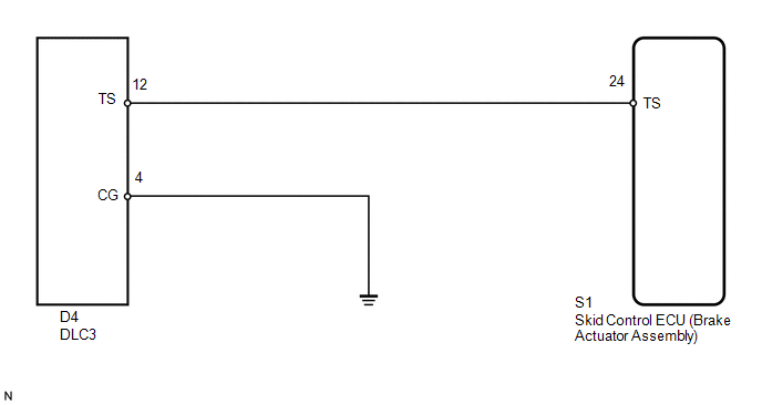
WIRING DIAGRAM
CAUTION / NOTICE / HINT
NOTICE:
When replacing the skid control ECU (brake actuator assembly), perform zero point
calibration and store system information (See page
.gif) ).
).
PROCEDURE
|
1. |
CHECK HARNESS AND CONNECTOR (BRAKE ACTUATOR ASSEMBLY - TS of DLC3) |
(a) Turn the ignition switch off.
(b) Disconnect the S1 skid control ECU (brake actuator assembly) connector.
(c) Measure the resistance according to the value(s) in the table below.
Standard Resistance:
|
Tester Connection |
Condition |
Specified Condition |
|---|---|---|
|
S1-24 (TS) - D4-12 (TS) |
Always |
Below 1 Ω |
|
S1-24 (TS) or D4-12 (TS) - Body ground |
Always |
10 kΩ or higher |
| NG | .gif) |
REPAIR OR REPLACE HARNESS OR CONNECTOR |
|
.gif)
|
2. |
CHECK HARNESS AND CONNECTOR (CG of DLC3 - BODY GROUND) |
|
(a) Measure the resistance according to the value(s) in the table below. Standard Resistance:
|
|
.png)
| OK | |
REPLACE BRAKE ACTUATOR ASSEMBLY |
| NG | |
REPAIR OR REPLACE HARNESS OR CONNECTOR |
 VSC Buzzer Circuit
DESCRIPTION
The skid control ECU (brake actuator assembly) is connected to the combination
meter via CAN communication.
The combination meter has a built-in VSC warning buzzer:
Sounds inte ...
 VSC OFF Switch Circuit
DESCRIPTION
The skid control ECU assembly is connected to the combination meter assembly
via CAN communication.
Pressing the VSC OFF switch turns off TRAC operation, and pressing and holding
thi ...
Other materials:
Tires
Replace or rotate tires in accordance with maintenance schedules and treadwear.
■ Checking tire
1. New tread
2. Treadwear indicator
3. Worn tread
The location of treadwear indicators is shown by the “TWI” or “
” marks, etc., molded on the sidewall of each tire.
Check spare ti ...
Listening to a USB memory device
Connecting a USB memory device enables you to enjoy music from the vehicle
speakers.
Select “USB” on the “Select Audio Source” screen.
Connecting a USB memory device
Audio control screen
1. “Select Audio Source” screen appears
2. Displaying the folder list
3. Random playback
4 ...
On-vehicle Inspection
ON-VEHICLE INSPECTION
PROCEDURE
1. INSPECT REAR AIRBAG SENSOR (for Vehicle not Involved in Collision)
(a) Perform a diagnostic system check (See page
).
2. INSPECT REAR AIRBAG SENSOR (for Vehicle Involved in Collision and Airbag has
not Deployed)
CAUTION:
For rear airbag sensor removal and ...
