Toyota Tacoma (2015-2018) Service Manual: Unlock Warning Switch
Components
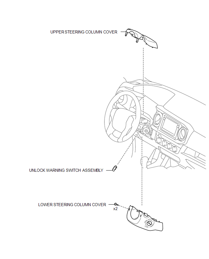
COMPONENTS
ILLUSTRATION
Inspection
INSPECTION
PROCEDURE
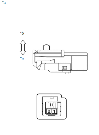
1. INSPECT UNLOCK WARNING SWITCH ASSEMBLY
(a) Check the resistance.
|
(1) Measure the resistance according to the value(s) in the table below. Text in Illustration
Standard Resistance:
|
|
Removal
REMOVAL
PROCEDURE
1. REMOVE LOWER STEERING COLUMN COVER
.gif)
2. REMOVE UPPER STEERING COLUMN COVER
3. REMOVE UNLOCK WARNING SWITCH ASSEMBLY
|
(a) Insert the key into the ignition key cylinder. Text in Illustration
|
|
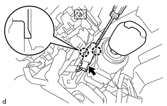
(b) Disconnect the connector.
(c) Using a screwdriver with its tip wrapped in protective tape, disengage the 2 claws to remove the unlock warning switch assembly.
Installation
INSTALLATION
PROCEDURE
1. INSTALL UNLOCK WARNING SWITCH ASSEMBLY
(a) Engage the 2 claws to install the unlock warning switch assembly.
(b) Connect the connector.
(c) Remove the key from the ignition key cylinder.
2. INSTALL UPPER STEERING COLUMN COVER
.gif)
3. INSTALL LOWER STEERING COLUMN COVER
 Transmitter Battery(w/ Smart Key System)
Replacement
REPLACEMENT
CAUTION / NOTICE / HINT
NOTICE:
Take extra care when handling these precision electronic components.
PROCEDURE
1. REMOVE TRANSMITTER BATTERY
(a) Push the re ...
 Wireless Door Lock Buzzer
Components
COMPONENTS
ILLUSTRATION
Removal
REMOVAL
PROCEDURE
1. REMOVE WIRELESS DOOR LOCK BUZZER
(a) Disconnect the connector.
(b) Us ...
Other materials:
Inspection
INSPECTION
PROCEDURE
1. INSPECT OIL PUMP RELIEF VALVE
(a) Coat the oil pump relief valve with engine oil and check that it
falls smoothly into the valve hole by its own weight.
If the valve does not fall smoothly, replace the timing chain cover assembly.
...
On-vehicle Inspection
ON-VEHICLE INSPECTION
PROCEDURE
1. CHECK BATTERY CONDITION
NOTICE:
If the battery is weak or if the engine is difficult to start, recharge the battery
and perform inspections again before returning the vehicle to the customer.
(a) Check the battery for damage or deformation. If severe damage, ...
Removal
REMOVAL
CAUTION / NOTICE / HINT
NOTICE:
If one of the camshaft timing gear bolts is already removed, do not remove any
other camshaft timing gear bolts.
PROCEDURE
1. REMOVE NO. 2 ENGINE UNDER COVER SUB-ASSEMBLY (w/ Off Road Package)
2. REMOVE NO. 1 ENGINE UNDER COVER SUB-ASSEMBLY
3. REMOVE ...
