COMPONENTS
ILLUSTRATION
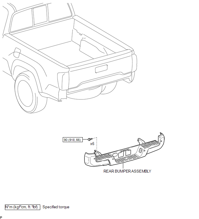
ILLUSTRATION
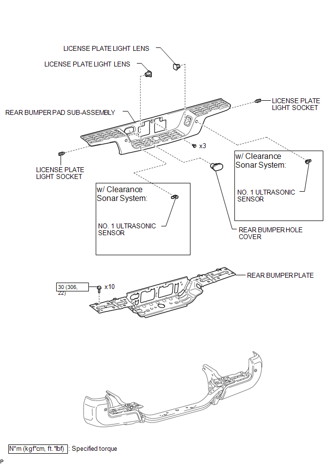
ILLUSTRATION
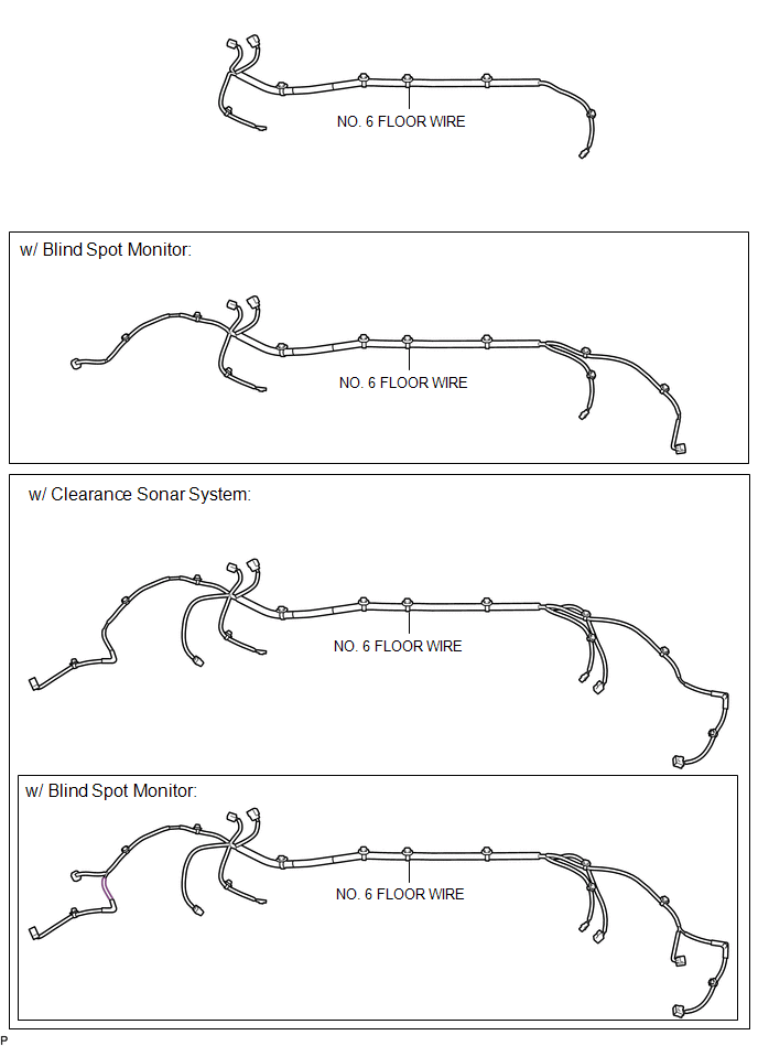
ILLUSTRATION
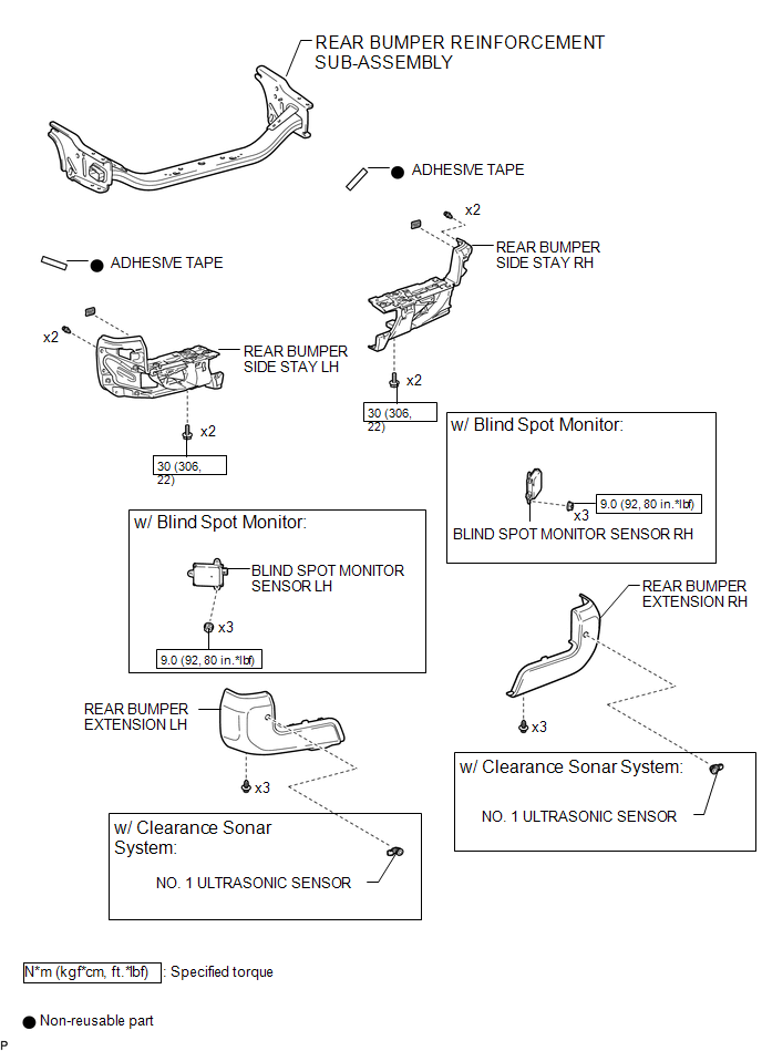
Related Tacoma materials
Starter Relay Circuit Short to Battery (P061512)
DESCRIPTION
While the engine is being cranked, positive battery voltage is applied to terminal
STA of the ECM. If the ECM detects the starter control (STA) signal while the vehicle
is being driven, it determines that there is a malfunction in the STA circuit. The
ECM then illuminates the MIL ...
Fail-safe Chart
FAIL-SAFE CHART
FAIL-SAFE FUNCTION
(a) When a malfunction occurs in the lane departure alert system, a message will
be displayed on the multi-information display in the combination meter assembly
and the lane departure alert system will be disabled depending on the malfunction.
War ...
Installation
INSTALLATION
PROCEDURE
1. INSTALL DIFFERENTIAL SIDE GEAR SHAFT OIL SEAL
(a) Using SST and a hammer, install a new oil seal.
SST: 09554-30011
(b) Coat the oil seal lip with MP grease.
2. INSTALL FRONT DRIVE SHAFT ASSEMBLY LH
Click here ...