Toyota Tacoma (2015-2018) Service Manual: Wireless Door Lock Buzzer
Components
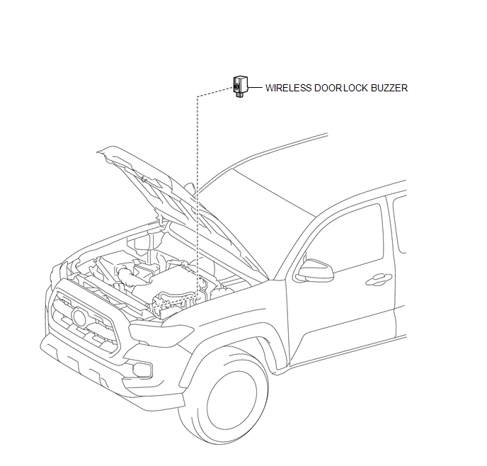
COMPONENTS
ILLUSTRATION
Removal
REMOVAL
PROCEDURE
1. REMOVE WIRELESS DOOR LOCK BUZZER
|
(a) Disconnect the connector. |
|
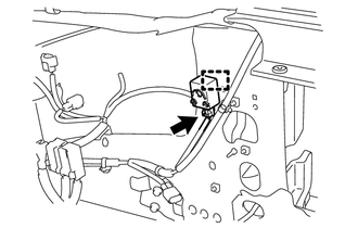
(b) Using a clip remover, disengage the clamp to remove the wireless door lock buzzer.
Installation
INSTALLATION
PROCEDURE
1. INSTALL WIRELESS DOOR LOCK BUZZER
(a) Engage the clamp to install the wireless door lock buzzer.
(b) Connect the connector.
 Unlock Warning Switch
Components
COMPONENTS
ILLUSTRATION
Inspection
INSPECTION
PROCEDURE
1. INSPECT UNLOCK WARNING SWITCH ASSEMBLY
(a) Check the resistance.
(1) Measure the resistance according to ...

Other materials:
Installation
INSTALLATION
PROCEDURE
1. INSTALL WATER INLET WITH THERMOSTAT SUB-ASSEMBLY
(a) Install a new gasket to the water inlet with thermostat sub-assembly.
(b) Install the water inlet with thermostat sub-assembly to the timing chain
cover assembly with the 2 bolts and nut.
Torque:
10 N·m {102 kgf ...
Differential System(w/o Differential Lock)
Precaution
PRECAUTION
1. Before disassembly, clean the outside of the front and rear differential assembly
and remove any sand and mud to prevent it from entering the assembly during disassembly
and installation.
2. When removing connected parts made of a light alloy, such as front and rear ...
Terminals Of Ecu
TERMINALS OF ECU
1. ECM
Terminal No. (Symbol)
Wiring Color
Terminal Description
Condition
Specified Condition
E14-20 (TC) - E11-1 (E1)
G - W-B
DTC output signal
Ignition switch ON
...
