Toyota Tacoma (2015-2018) Service Manual: Speed Sensor
Components
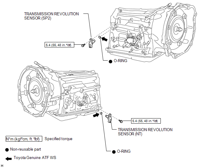
COMPONENTS
ILLUSTRATION
Removal
REMOVAL
PROCEDURE
1. REMOVE TRANSMISSION REVOLUTION SENSOR (NT)
|
(a) Disconnect the transmission revolution sensor (NT) connector. |
|
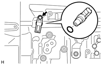
(b) Remove the bolt and transmission revolution sensor (NT).
(c) Remove the O-ring from the transmission revolution sensor (NT).
2. REMOVE TRANSMISSION REVOLUTION SENSOR (SP2)
|
(a) Disconnect the transmission revolution sensor (SP2) connector. |
|
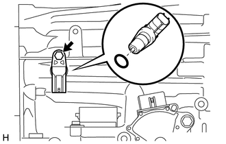
(b) Remove the bolt and transmission revolution sensor (SP2).
(c) Remove the O-ring from the transmission revolution sensor (SP2).
Inspection
INSPECTION
PROCEDURE
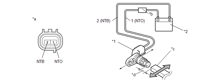
1. INSPECT TRANSMISSION REVOLUTION SENSOR (NT)
(a) Connect the battery to the transmission revolution sensor (NT) as shown in the illustration.
 Text in Illustration
|
*1 |
Transmission Revolution Sensor (NT) |
*2 |
Battery |
|
*a |
Component without harness connected (Transmission Revolution Sensor (NT)) |
*b |
Ammeter |
|
*c |
Magnet |
*d |
5 mm (0.197 in.) or less |
(b) Wave a magnetic object left and right in front of the transmission revolution sensor (NT) tip (5 mm (0.197 in.) or less) to change the high/low signals while measuring the current.
NOTICE:
Make sure to wave the magnetic object during the inspection. The current will not change without waving the magnetic object as indicated by the arrow in the illustration.
(c) Measure the current according to the value(s) in the table below.
Standard Current:
|
Tester Connection |
Condition |
Specified Condition |
|---|---|---|
|
1 (NTO) - 2 (NTB) |
Low signal |
4 to 8 mA |
|
High signal |
12 to 16 mA |
If the result is not as specified, replace the transmission revolution sensor (NT).
2. INSPECT TRANSMISSION REVOLUTION SENSOR (SP2)
(a) Connect the battery to the transmission revolution sensor (SP2) as shown in the illustration.
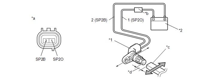 Text in Illustration
|
*1 |
Transmission Revolution Sensor (SP2) |
*2 |
Battery |
|
*a |
Component without harness connected (Transmission Revolution Sensor (SP2)) |
*b |
Ammeter |
|
*c |
Magnet |
*d |
5 mm (0.197 in.) or less |
(b) Wave a magnetic object left and right in front of the transmission revolution sensor (SP2) tip (5 mm (0.197 in.) or less) to change the high/low signals while measuring the current.
NOTICE:
Make sure to wave the magnetic object during the inspection. The current will not change without waving the magnetic object as indicated by the arrow in the illustration.
(c) Measure the current according to the value(s) in the table below.
Standard Current:
|
Tester Connection |
Condition |
Specified Condition |
|---|---|---|
|
1 (SP2O) - 2 (SP2B) |
Low signal |
4 to 8 mA |
|
High signal |
12 to 16 mA |
If the result is not as specified, replace the transmission revolution sensor (SP2).
Installation
INSTALLATION
PROCEDURE
1. INSTALL TRANSMISSION REVOLUTION SENSOR (SP2)
(a) Coat a new O-ring with ATF and install it to the transmission revolution sensor (SP2).
(b) Install the transmission revolution sensor (SP2) with the bolt.
Torque:
5.4 N·m {55 kgf·cm, 48 in·lbf}
(c) Connect the transmission revolution sensor (SP2) connector.
2. INSTALL TRANSMISSION REVOLUTION SENSOR (NT)
(a) Coat a new O-ring with ATF and install it to the transmission revolution sensor (NT).
(b) Install the transmission revolution sensor (NT) with the bolt.
Torque:
5.4 N·m {55 kgf·cm, 48 in·lbf}
(c) Connect the transmission revolution sensor (NT) connector.
 Reassembly
REASSEMBLY
PROCEDURE
1. INSTALL INDICATOR LIGHT WIRE SUB-ASSEMBLY
(a) Connect the connector to install the indicator light wire sub-assembly
to the shift position indicator.
...
 Torque Converter And Drive Plate
Inspection
INSPECTION
PROCEDURE
1. INSPECT TORQUE CONVERTER ASSEMBLY
(a) Inspect the one-way clutch.
(1) Press on the spline of the stator with a finger and rotate the spline. Check
that the ...
Other materials:
Fuel Pressure Sensor
Components
COMPONENTS
ILLUSTRATION
Inspection
INSPECTION
PROCEDURE
1. INSPECT FUEL DELIVERY PIPE SUB-ASSEMBLY (FUEL PRESSURE SENSOR)
NOTICE:
Do not remove the fuel pressure sensor from the fuel delivery pipe sub-assembly.
If a fuel pressure sensor is removed, replace the ...
Installation
INSTALLATION
CAUTION / NOTICE / HINT
HINT:
Use the same procedure for the RH and LH sides.
The procedure listed below is for the LH side.
PROCEDURE
1. INSTALL REAR SPEAKER ASSEMBLY
(a) Install the rear speaker assembly with the 3 screws.
NOTICE:
Do not touch the cone part o ...
Customize Parameters
CUSTOMIZE PARAMETERS
PROCEDURE
1. CUSTOMIZE POWER WINDOW CONTROL SYSTEM
HINT:
The following items can be customized.
NOTICE:
When the customer requests a change in a function, first make sure that
the function can be customized.
Record the current settings before customizing.
...
