Toyota Tacoma (2015-2018) Service Manual: System Diagram
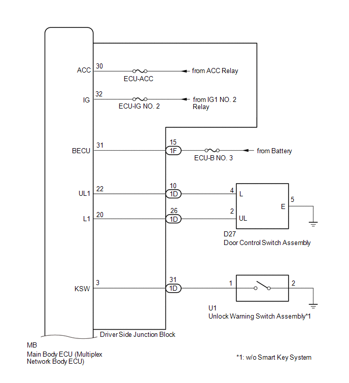
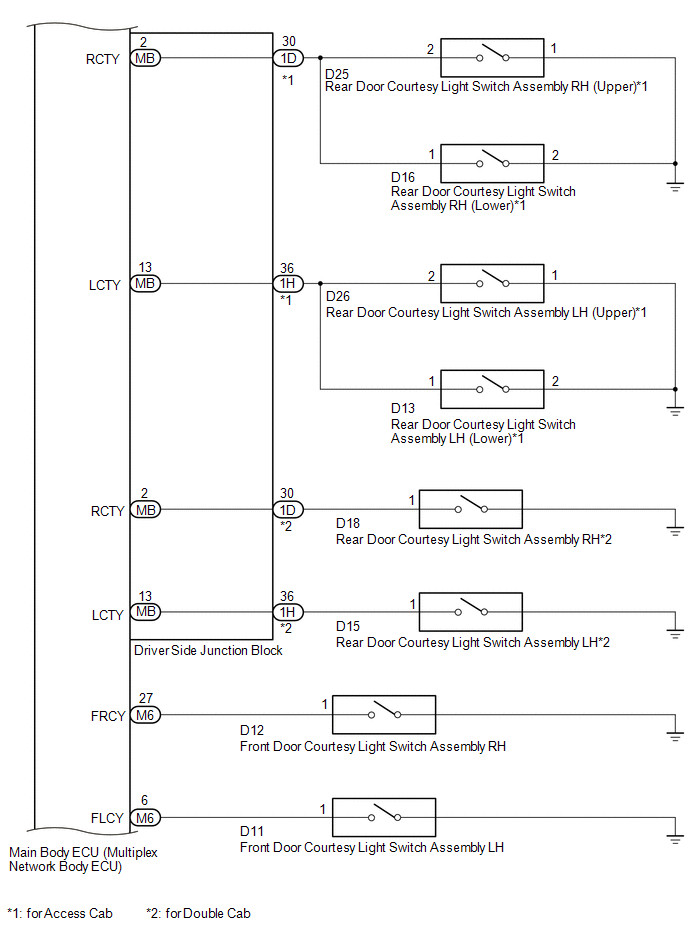
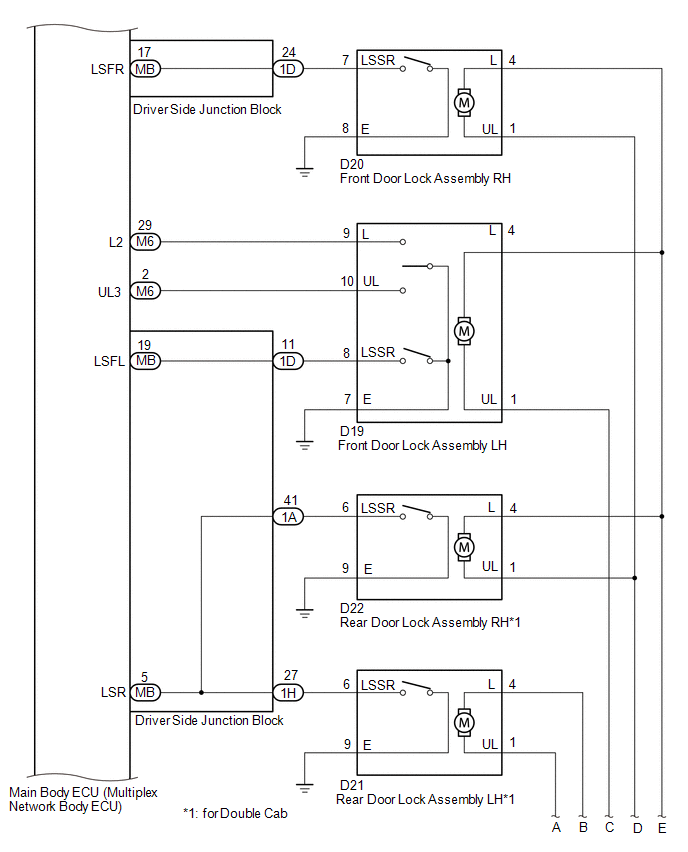
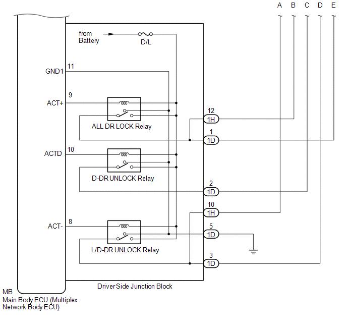
SYSTEM DIAGRAM
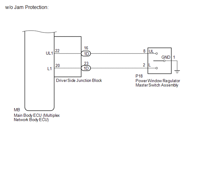
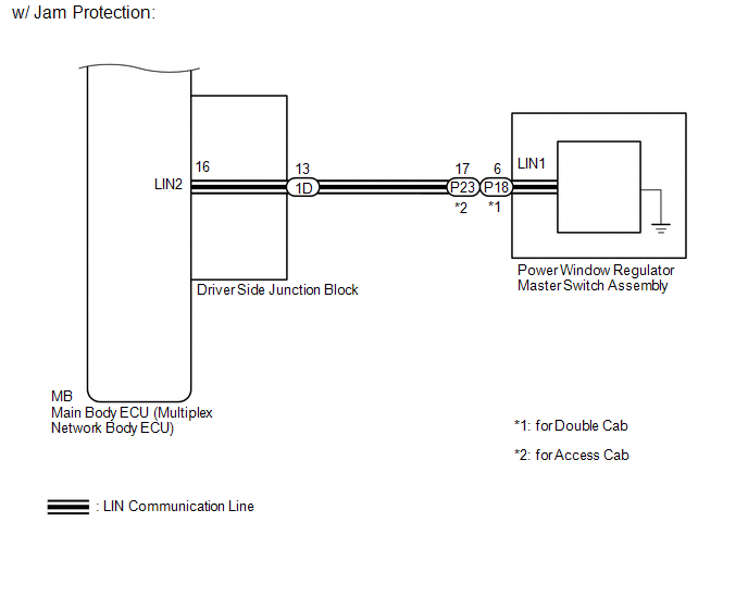 Communication Table
|
Sender |
Receiver |
Signal |
Communication Method |
|---|---|---|---|
|
Power window regulator master switch assembly*1 |
Main Body ECU (Multiplex Network Body ECU) |
Door control switch signal |
LIN |
- *1: w/ Jam Protection
 System Description
SYSTEM DESCRIPTION
1. POWER DOOR LOCK CONTROL SYSTEM DESCRIPTION
(a) The power door lock system locks/unlocks all the doors.
The main body ECU (multiplex network body ECU) receives lock/unlock requ ...
 Customize Parameters
CUSTOMIZE PARAMETERS
1. CUSTOMIZE POWER DOOR LOCK CONTROL SYSTEM
HINT:
The following items can be customized.
NOTICE:
When the customer requests a change in a function, first make sure th ...
Other materials:
Precaution
PRECAUTION
1. EXPRESSIONS OF IGNITION SWITCH
HINT:
The type of ignition switch used on this model differs according to the specifications
of the vehicle. The expressions listed in the table below are used in this section.
Expression
Ignition Switch
(Position)
...
Installation
INSTALLATION
PROCEDURE
1. REMOVE MONOLITHIC CONVERTER PROTECTOR
(a) Install the upper monolithic converter protector and lower monolithic converter
protector with the 2 bolts and 2 nuts.
Torque:
11 N·m {107 kgf·cm, 8 ft·lbf}
(b) Install the clamp with the bolt as shown in the ...
Removal
REMOVAL
PROCEDURE
1. REMOVE STEERING PAD
(See page
)
2. REMOVE STEERING WHEEL ASSEMBLY
3. REMOVE LOWER STEERING COLUMN COVER
4. REMOVE UPPER STEERING COLUMN COVER
5. REMOVE SPIRAL CABLE SUB-ASSEMBLY WITH SENSOR
(a) Slide the slider and disconnect the airbag connect ...
