Toyota Tacoma (2015-2018) Service Manual: Transfer Case Front Oil Seal
Components
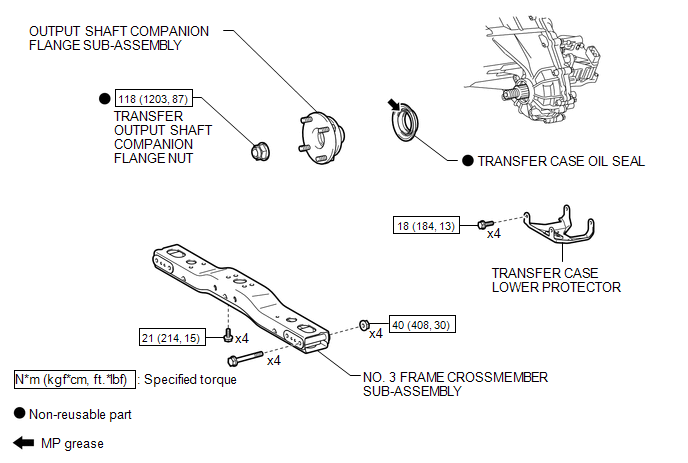
COMPONENTS
ILLUSTRATION
Replacement
REPLACEMENT
PROCEDURE
1. DRAIN TRANSFER OIL
.gif)
2. SUPPORT TRANSMISSION ASSEMBLY
3. REMOVE NO. 3 FRAME CROSSMEMBER SUB-ASSEMBLY
4. REMOVE TRANSFER CASE LOWER PROTECTOR
5. REMOVE FRONT PROPELLER SHAFT ASSEMBLY
(See page )
6. REMOVE OUTPUT SHAFT COMPANION FLANGE SUB-ASSEMBLY
7. REMOVE TRANSFER CASE OIL SEAL
|
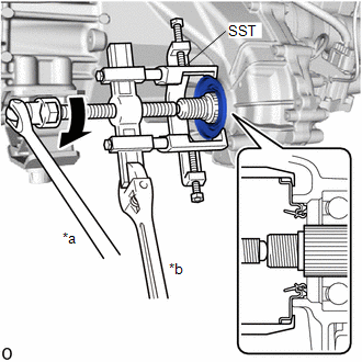
(a) Using SST, remove the transfer case oil seal. SST: 09950-40011 09951-04020 09952-04010 09953-04030 09954-04010 09955-04031 09957-04010 09958-04011 Text in Illustration
NOTICE: Apply a lubricant to the threads and end of SST. |
|
8. INSTALL TRANSFER CASE OIL SEAL
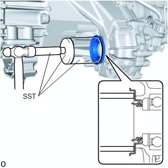
(a) Coat the lip of a new transfer case oil seal with MP grease.
|
(b) Using SST and a hammer, install the transfer case oil seal until its metal ring contacts the case. SST: 09710-30041 09710-03221 SST: 09950-60010 09951-00600 09951-00650 09952-06010 SST: 09950-70010 09951-07150 |
|
9. INSTALL OUTPUT SHAFT COMPANION FLANGE SUB-ASSEMBLY
10. INSTALL FRONT PROPELLER SHAFT ASSEMBLY
(See page )
11. INSTALL TRANSFER CASE LOWER PROTECTOR
12. INSTALL NO. 3 FRAME CROSSMEMBER SUB-ASSEMBLY
13. ADD TRANSFER OIL
14. INSPECT FOR TRANSFER OIL LEAK
 Installation
INSTALLATION
CAUTION / NOTICE / HINT
CAUTION:
Be sure to perform this procedure with several people as the transfer assembly
is very heavy.
PROCEDURE
1. INSTALL TRANSFER CASE LOWER PROTECTOR
( ...
 Transfer Case Rear Oil Seal
Components
COMPONENTS
ILLUSTRATION
Replacement
REPLACEMENT
PROCEDURE
1. DRAIN TRANSFER OIL
2. REMOVE PROPELLER WITH CENTER BEARING SHAFT ASSEMBLY
(See page )
3. REMOVE OUTPUT SHAFT ...
Other materials:
Tire Pressure Monitor ECU Communication Stop (C2179/79)
DESCRIPTION
The main body ECU (multiplex network body ECU) sends signals to the tire pressure
warning ECU and receiver via a direct line.
DTC No.
Detection Item
DTC Detection Condition
Trouble Area
Note
C2179/79
T ...
Removal
REMOVAL
PROCEDURE
1. REMOVE FRONT WIPER ARM HEAD CAP
(a) Using a screwdriver with its tip wrapped in protective tape, disengage
the 3 claws to remove the front wiper arm head cap.
Text in Illustration
*a
Protective Tape
HINT ...
Removal
REMOVAL
PROCEDURE
1. REMOVE PROPELLER SHAFT WITH CENTER BEARING ASSEMBLY
(a) Place matchmarks on the propeller shaft flange and differential flange.
Text in Illustration
*a
Matchmark
...
