Toyota Tacoma (2015-2018) Service Manual: Transfer Case Rear Oil Seal
Components
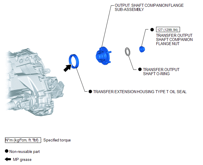
COMPONENTS
ILLUSTRATION
Replacement
REPLACEMENT
PROCEDURE
1. DRAIN TRANSFER OIL
.gif)
2. REMOVE PROPELLER WITH CENTER BEARING SHAFT ASSEMBLY
(See page )
3. REMOVE OUTPUT SHAFT COMPANION FLANGE SUB-ASSEMBLY
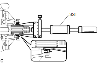
4. REMOVE TRANSFER EXTENSION HOUSING TYPE T OIL SEAL
|
(a) Using SST, remove the transfer extension housing type T oil seal. SST: 09308-00010 NOTICE: Be careful not to damage the transfer extension housing type T oil seal and extension housing contact surface. |
|
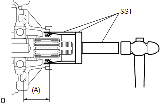
5. INSTALL TRANSFER EXTENSION HOUSING TYPE T OIL SEAL
(a) Coat the lip of a new transfer extension housing type T oil seal with MP grease.
|
(b) Using SST and a hammer, install the transfer extension housing type T oil seal as shown in the illustration. SST: 09631-12090 SST: 09950-60010 09951-00600 SST: 09950-70010 09951-07100 Drive in depth (A): 48.5 to 49.5 mm (1.910 to 1.948 in.) NOTICE: Be careful not to damage the transfer extension housing type T oil seal. |
|
6. INSTALL OUTPUT SHAFT COMPANION FLANGE SUB-ASSEMBLY
7. INSTALL PROPELLER WITH CENTER BEARING SHAFT ASSEMBLY
(See page )
8. ADD TRANSFER OIL
9. CHECK FOR TRANSFER OIL LEAK
 Transfer Case Front Oil Seal
Components
COMPONENTS
ILLUSTRATION
Replacement
REPLACEMENT
PROCEDURE
1. DRAIN TRANSFER OIL
2. SUPPORT TRANSMISSION ASSEMBLY
3. REMOVE NO. 3 FRAME CROSSMEMBER SUB-ASSEMBLY
4. ...
 Transfer Oil
On-vehicle Inspection
ON-VEHICLE INSPECTION
PROCEDURE
1. CHECK TRANSFER OIL
(a) Remove the filler plug and gasket.
Text in Illustration
*1
Fill ...
Other materials:
Radio Receiver Assembly Communication Stop Mode
DESCRIPTION
Detection Item
Symptom
Trouble Area
Radio Receiver Assembly Communication Stop Mode
Either condition is met:
Communication stop for "Display and Navigation (AVN1)" is indicated
on the "Commun ...
Precaution
PRECAUTION
1. IGNITION SWITCH EXPRESSIONS
(a) The type of ignition switch used on this model differs according to the specifications
of the vehicle. The expressions listed in the table below are used in this section.
Expression
Ignition Switch (Position)
Engine ...
Components
COMPONENTS
ILLUSTRATION
*1
FORWARD RECOGNITION CAMERA
*2
FORWARD RECOGNITION LATCH
*3
NO. 1 FORWARD RECOGNITION COVER
-
-
...
