Toyota Tacoma (2015-2018) Service Manual: Driver Side Door Entry Unlock Function does not Operate
DESCRIPTION
If the entry unlock function does not operate for the driver door only, but the entry lock function operates, the request code is being transmitted properly from the driver door. In this case, there may be a problem related to the touch sensor (connection between the certification ECU (smart key ECU assembly) and front door outside handle assembly LH [unlock sensor]).
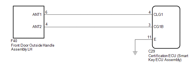
WIRING DIAGRAM
CAUTION / NOTICE / HINT
NOTICE:
- The smart key system (for Entry Function) uses a multiplex communication
system (LIN communication system) and the CAN communication system. Inspect
the communication function by following How to Proceed with Troubleshooting.
Troubleshoot the smart key system (for Entry Function) after confirming
that the communication systems are functioning properly (See page
.gif) ).
). - When using the Techstream with the engine switch off, connect the Techstream to the DLC3 and turn a courtesy light switch on and off at intervals of 1.5 seconds or less until communication between the Techstream and the vehicle begins. Then select the vehicle type under manual mode and enter the following menus: Body Electrical / Smart Key. While using the Techstream, periodically turn a courtesy light switch on and off at intervals of 1.5 seconds or less to maintain communication between the Techstream and the vehicle.
- Check that there are no electrical key transmitter sub-assemblies in the vehicle.
- Before performing the inspection, check that DTC B1242 (wireless door
lock control) is not output (See page ).
- Before replacing the certification ECU (smart key ECU assembly), refer
to the smart key system (for Entry Function) precaution (See page
).
- After repair, confirm that no DTCs are output by performing the "DTC Output Confirmation Operation".
PROCEDURE
|
1. |
CHECK POWER DOOR LOCK CONTROL SYSTEM |
(a) When the door control switch on the power window regulator master switch
assembly is operated, check that the doors unlock and lock according to the switch
operation (See page ).
OK:
Door locks operate normally.
| NG | .gif) |
GO TO POWER DOOR LOCK CONTROL SYSTEM |
|
.gif)
|
2. |
READ VALUE USING TECHSTREAM (FL DOOR LOCK POS) |
(a) Connect the Techstream to the DLC3.
(b) Turn the engine switch on (IG).
(c) Turn the Techstream on.
(d) Enter the following menus: Body Electrical / Main Body / Data List.
(e) Read the Data List according to the display on the Techstream.
Main Body|
Tester Display |
Measurement Item/Range |
Normal Condition |
Diagnostic Note |
|---|---|---|---|
|
FL Door Lock Pos |
Front door LH unlock detection switch signal / UNLOCK or LOCK |
UNLOCK: Front door LH unlocked LOCK: Front door LH locked |
- |
OK:
The Techstream display changes correctly in response to the lock/unlock operation of the front LH door.
| NG | |
GO TO LIGHTING SYSTEM (Proceed to Door Unlock Detection Switch Circuit) |
|
|
3. |
READ VALUE USING TECHSTREAM (D-DOOR TOUCH SENSOR) |
(a) Connect the Techstream to the DLC3.
(b) Turn the engine switch on (IG).
(c) Turn the Techstream on.
(d) Enter the following menus: Body Electrical / Smart Key / Data List.
(e) Read the Data List according to the display on the Techstream.
Smart Key|
Tester Display |
Measurement Item/Range |
Normal Condition |
Diagnostic Note |
|---|---|---|---|
|
D-Door Touch Sensor |
Driver door touch sensor (unlock sensor) / ON or OFF |
ON: Driver door touch sensor (unlock sensor) touched OFF: Driver door touch sensor (unlock sensor) not touched |
|
OK:
The Techstream display changes correctly in response to the operation of the front door outside handle assembly LH.
Result|
Result |
Proceed to |
|---|---|
|
NG |
A |
|
OK |
B |
| B | |
REPLACE CERTIFICATION ECU (SMART KEY ECU ASSEMBLY) |
|
|
4. |
CHECK HARNESS AND CONNECTOR (CERTIFICATION ECU (SMART KEY ECU ASSEMBLY) - FRONT DOOR OUTSIDE HANDLE ASSEMBLY LH) |
(a) Disconnect the C29 certification ECU (smart key ECU assembly) connector.
(b) Disconnect the F40 front door outside handle assembly LH connector.
(c) Measure the resistance according to the value(s) in the table below.
Standard Resistance:
|
Tester Connection |
Condition |
Specified Condition |
|---|---|---|
|
C29-4 (CLG1) - F40-6 (ANT1) |
Always |
Below 1 Ω |
|
C29-3 (CG1B) - F40-4 (ANT2) |
Always |
Below 1 Ω |
|
C29-4 (CLG1) or F40-6 (ANT1) - Body ground |
Always |
10 kΩ or higher |
|
C29-3 (CG1B) or F40-4 (ANT2) - Body ground |
Always |
10 kΩ or higher |
(d) Reconnect the F40 front door outside handle assembly LH connector.
(e) Reconnect the C29 certification ECU (smart key ECU assembly) connector.
| NG | |
REPAIR OR REPLACE HARNESS OR CONNECTOR |
|
|
5. |
CHECK FRONT DOOR OUTSIDE HANDLE ASSEMBLY LH (INPUT TO DRIVER DOOR UNLOCK SENSOR) |
(a) Using an oscilloscope, check the waveform.
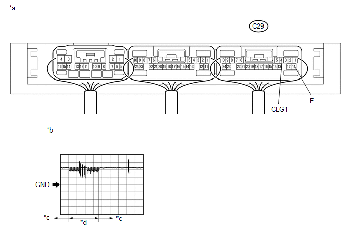 Text in Illustration
|
*a |
Component with harness connected (Certification ECU (smart key ECU assembly)) |
*b |
Waveform 1 |
|
*c |
Unlock sensor not touched |
*d |
Unlock sensor touched |
OK:
|
Tester Connection |
Switch Condition |
Tool Setting |
Specified Condition |
|---|---|---|---|
|
C29-4 (CLG1) - C29-11 (E) |
Procedure:
|
5 V/DIV., 40 ms/DIV. |
Pulse generation (See waveform 1) |
| OK | |
REPLACE CERTIFICATION ECU (SMART KEY ECU ASSEMBLY) |
| NG | |
REPLACE FRONT DOOR OUTSIDE HANDLE ASSEMBLY LH |
 Driver Side Door Entry Lock and Unlock Functions do not Operate
DESCRIPTION
If the entry lock and unlock functions do not operate for the driver door only,
the request code may not be being transmitted from the driver door or the front
door outside handle ass ...
 Driver Side Door Entry Lock Function does not Operate
DESCRIPTION
If the entry lock function does not operate for the driver door only, but the
entry unlock function operates, the request code is being transmitted properly from
the driver door. In t ...
Other materials:
Rear Differential Lock Position SW Stuck OFF (P17BB)
DESCRIPTION
This DTC is output when an OFF malfunction of the differential lock indicator
switch is detected.
DTC No.
Detection Item
DTC Detection Condition
Trouble Area
P17BB
Rear Differential Lock Position SW Stuck OFF
...
Road Test
ROAD TEST
PROBLEM SYMPTOM CONFIRMATION
HINT:
The dynamic radar cruise control system has 2 cruise control modes:
constant speed control mode and vehicle-to-vehicle distance control mode.
Vehicle-to-vehicle distance control mode is selected by default when
the dyna ...
Motor Circuit Malfunction (C1428)
DESCRIPTION
DTC No.
Detection Item
DTC Detection Condition
Trouble Area
C1428
Motor Circuit Malfunction
With the motor relay and motor fail-safe relay OFF, open or short in
motor circuit continues for 2 seconds o ...
