Toyota Tacoma (2015-2018) Service Manual: TRAC OFF Indicator Light does not Come ON
DESCRIPTION
Refer to TRAC OFF Indicator Light Remains ON (See page
.gif) ).
).
WIRING DIAGRAM
Refer to TRAC OFF Indicator Light Remains ON (See page
).
CAUTION / NOTICE / HINT
NOTICE:
- When replacing the skid control ECU (master cylinder solenoid), perform
calibration (See page
).
- Inspect the fuses for circuits related to this system before performing the following inspection procedure.
PROCEDURE
|
1. |
CHECK CAN COMMUNICATION SYSTEM |
| NG | .gif) |
GO TO CAN COMMUNICATION SYSTEM (HOW TO PROCEED WITH TROUBLESHOOTING) |
|
.gif)
|
2. |
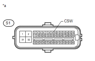
INSPECT SKID CONTROL ECU (CSW TERMINAL) |
(a) Disconnect the S1 skid control ECU (master cylinder solenoid) connector.
|
(b) Measure the resistance according to the value(s) in the table below. Standard Resistance:
|
|
(c) Reconnect the S1 skid control ECU (master cylinder solenoid) connector.
| NG | |
GO TO STEP 4 |
|
|
3. |
READ VALUE USING TECHSTREAM (TRAC/VSC OFF MODE) |
(a) Turn the ignition switch off.
(b) Connect the Techstream to the DLC3.
(c) Turn the ignition switch to ON.
(d) Turn the Techstream on.
(e) Enter the following menus: Chassis / ABS/VSC/TRAC / Data List.
ABS/VSC/TRAC|
Tester Display |
Measurement Item |
Control Range |
Diagnostic Note |
|---|---|---|---|
|
TRAC/VSC Off Mode |
TRAC/VSC off mode/ Normal, TRC OFF, Unknown or VSC OFF |
Normal: Normal mode TRC OFF: TRAC OFF mode VSC OFF: VSC OFF mode |
- |
(f) Check that the mode display changes according to VSC OFF switch operation.
OK:
Display changes according to switch operation.
| OK | |
GO TO METER / GAUGE SYSTEM (HOW TO PROCEED WITH TROUBLESHOOTING) |
| NG | |
REPLACE MASTER CYLINDER SOLENOID |
|
4. |
INSPECT VSC OFF SWITCH |
| NG | |
REPLACE VSC OFF SWITCH |
|
|
5. |
INSPECT ROOF CONSOLE BOX ASSEMBLY (MASTER CYLINDER SOLENOID - VSC OFF SWITCH) |
| A | |
REPAIR OR REPLACE HARNESS OR CONNECTOR (MASTER CYLINDER SOLENOID - ROOF CONSOLE BOX ASSEMBLY) |
| B | |
REPLACE ROOF CONSOLE BOX ASSEMBLY |
| C | |
REPLACE ROOF CONSOLE BOX ASSEMBLY |
 Brake Warning Light Remains ON
DESCRIPTION
The BRAKE warning light comes on when brake fluid is insufficient, the parking
brake is applied or the EBD is defective.
WIRING DIAGRAM
CAUTION / NOTICE / HINT
NOTICE:
Whe ...
 TRAC OFF Indicator Light Remains ON
DESCRIPTION
In 2WD mode:
Operation of the VSC OFF switch changes the vehicle between normal mode,
TRAC OFF mode (AUTO LSD mode) and VSC OFF mode. During normal mode, pressing
the VS ...
Other materials:
Components
COMPONENTS
ILLUSTRATION
*A
for Type A
*B
for Type B
*C
for Type C
-
-
*1
MILLIMETER WAVE RADAR SENSOR ASSEMBLY
*2
MILLIMETER WAVE RADAR WIRE
...
Distance Control Switch Circuit
DESCRIPTION
The distance control switch is used to set the distance for vehicle-to-vehicle
distance control mode. The distance control switch is installed in the steering
pad switch assembly. The vehicle-to-vehicle distance set value can be changed by
operating the steering pad switch assembl ...
List of storage features
Glove box
Overhead console (Access Cab and
Double Cab models)
Bottle holders
Auxiliary boxes
Front console box (separated type
front seat only)
Cup holders
CAUTION
■Items that should not be left in the storage spaces
Do not leave glasses, lighters or spray cans in the stora ...
