Toyota Tacoma (2015-2018) Service Manual: Reverse Signal Circuit
DESCRIPTION
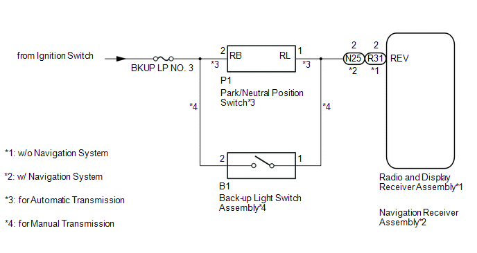
The radio and display receiver assembly*1 or navigation receiver assembly*2 receives a reverse signal from the park/neutral position switch*3 or the back-up light switch assembly*4.
- *1: w/o Navigation System
- *2: w/ Navigation System
- *3: for Automatic Transmission
- *4: for Manual Transmission
WIRING DIAGRAM
CAUTION / NOTICE / HINT
NOTICE:
Inspect the fuses for circuits related to this system before performing the following inspection procedure.
PROCEDURE
|
1. |
CONFIRM MODEL |
(a) Choose the model to be inspected.
Result|
Result |
Proceed to |
|---|---|
|
w/o Navigation System |
A |
|
w/ Navigation System |
B |
| B | .gif) |
GO TO STEP 8 |
|
.gif)
|
2. |
INSPECT RADIO AND DISPLAY RECEIVER ASSEMBLY (REVERSE SIGNAL) |
|
(a) Disconnect the radio and display receiver assembly connector. |
|
(b) Measure the voltage according to the value(s) in the table below.
Standard Voltage:
|
Tester Connection |
Switch Condition |
Specified Condition |
|---|---|---|
|
R31-2 (REV) - Body ground |
Ignition switch ON, shift lever in not R |
Below 1 V |
|
Ignition switch ON, shift lever in R |
11 to 14 V |
|
*a |
Rear view of wire harness connector (to Radio and Display Receiver Assembly) |
(c) Reconnect the radio and display receiver assembly connector.
| OK | |
PROCEED TO NEXT SUSPECTED AREA SHOWN IN PROBLEM SYMPTOMS TABLE |
|
|
3. |
SYSTEM CHECK |
(a) Check the vehicle specifications.
Result|
Result |
Proceed to |
|---|---|
|
for Automatic Transmission |
A |
|
for Manual Transmission |
B |
| B | |
GO TO STEP 6 |
|
|
4. |
INSPECT PARK/NEUTRAL POSITION SWITCH (IG SIGNAL) |
|
(a) Disconnect the park/neutral position switch connector. |
|
(b) Measure the voltage according to the value(s) in the table below.
Standard Voltage:
|
Tester Connection |
Switch Condition |
Specified Condition |
|---|---|---|
|
P1-2 (RB) - Body ground |
Ignition switch ON |
11 to 14 V |
|
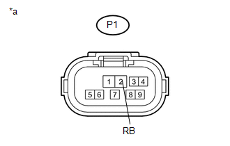
*a |
Front view of wire harness connector (to Park/Neutral Position Switch) |
(c) Reconnect the park/neutral position switch connector.
| NG | |
REPAIR OR REPLACE HARNESS OR CONNECTOR |
|
|
5. |
CHECK HARNESS AND CONNECTOR (RADIO AND DISPLAY RECEIVER ASSEMBLY - PARK/NEUTRAL POSITION SWITCH) |
(a) Disconnect the R31 radio and display receiver assembly connector.
(b) Disconnect the P1 park/neutral position switch connector.
(c) Measure the resistance according to the value(s) in the table below.
Standard Resistance:
|
Tester Connection |
Condition |
Specified Condition |
|---|---|---|
|
R31-2 (REV) - P1-1 (RL) |
Always |
Below 1 Ω |
|
R31-2 (REV) - Body ground |
Always |
10 kΩ or higher |
|
Result |
Proceed to |
|---|---|
|
NG |
A |
|
OK (for AC60F) |
B |
|
OK (for AC60E) |
C |
(d) Reconnect the radio and display receiver assembly connector.
(e) Reconnect the park/neutral position switch connector.
| A | |
REPAIR OR REPLACE HARNESS OR CONNECTOR |
| B | |
REPLACE PARK/NEUTRAL POSITION SWITCH |
| C | |
REPLACE PARK/NEUTRAL POSITION SWITCH |
|
6. |
INSPECT BACK-UP LIGHT SWITCH ASSEMBLY (IG SIGNAL) |
|
(a) Disconnect the back-up light switch assembly connector. |
|

(b) Measure the voltage according to the value(s) in the table below.
Standard Voltage:
|
Tester Connection |
Switch Condition |
Specified Condition |
|---|---|---|
|
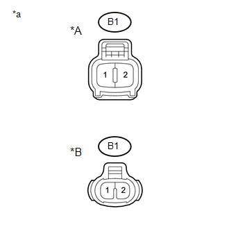
B1-2 - Body ground |
Ignition switch ON |
11 to 14 V |
|
*A |
for 2GR-FKS |
|
*B |
for 2TR-FE |
|
*a |
Front view of wire harness connector (to Back-up Light Switch Assembly) |
(c) Reconnect the back-up light switch assembly connector.
| NG | |
REPAIR OR REPLACE HARNESS OR CONNECTOR |
|
|
7. |
CHECK HARNESS AND CONNECTOR (RADIO AND DISPLAY RECEIVER ASSEMBLY - BACK-UP LIGHT SWITCH ASSEMBLY) |
(a) Disconnect the R31 radio and display receiver assembly connector.
(b) Disconnect the B1 back-up light switch assembly connector.
(c) Measure the resistance according to the value(s) in the table below.
Standard Resistance:
|
Tester Connection |
Condition |
Specified Condition |
|---|---|---|
|
R31-2 (REV) - B1-1 |
Always |
Below 1 Ω |
|
R31-2 (REV) - Body ground |
Always |
10 kΩ or higher |
|
Result |
Proceed to |
|---|---|
|
NG |
A |
|
OK (for R156F) |
B |
|
OK (for RC62F) |
C |
(d) Reconnect the radio and display receiver assembly connector.
(e) Reconnect the back-up light switch assembly connector.
| A | |
REPAIR OR REPLACE HARNESS OR CONNECTOR |
| C | |
REPLACE BACK-UP LIGHT SWITCH ASSEMBLY |
|
8. |
INSPECT NAVIGATION RECEIVER ASSEMBLY (REVERSE SIGNAL) |
|
(a) Disconnect the navigation receiver assembly connector. |
|
(b) Measure the voltage according to the value(s) in the table below.
Standard Voltage:
|
Tester Connection |
Switch Condition |
Specified Condition |
|---|---|---|
|
N25-2 (REV) - Body ground |
Ignition switch ON, shift lever in not R |
Below 1 V |
|
Ignition switch ON, shift lever in R |
11 to 14 V |
|
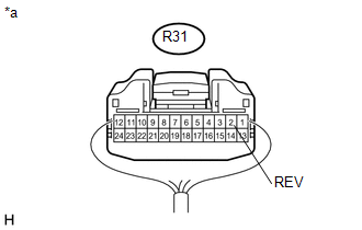
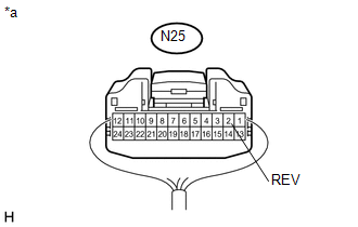
*a |
Rear view of wire harness connector (to Navigation Receiver Assembly) |
(c) Reconnect the navigation receiver assembly connector.
| OK | |
PROCEED TO NEXT SUSPECTED AREA SHOWN IN PROBLEM SYMPTOMS TABLE |
|
|
9. |
SYSTEM CHECK |
(a) Check the vehicle specifications.
Result|
Result |
Proceed to |
|---|---|
|
for Automatic Transmission |
A |
|
for Manual Transmission |
B |
| B | |
GO TO STEP 12 |
|
|
10. |
INSPECT PARK/NEUTRAL POSITION SWITCH (IG SIGNAL) |
|
(a) Disconnect the park/neutral position switch connector. |
|

(b) Measure the voltage according to the value(s) in the table below.
Standard Voltage:
|
Tester Connection |
Switch Condition |
Specified Condition |
|---|---|---|
|
P1-2 (RB) - Body ground |
Ignition switch ON |
11 to 14 V |
|
*a |
Front view of wire harness connector (to Park/Neutral Position Switch) |
(c) Reconnect the park/neutral position switch connector.
| NG | |
REPAIR OR REPLACE HARNESS OR CONNECTOR |
|
|
11. |
CHECK HARNESS AND CONNECTOR (NAVIGATION RECEIVER ASSEMBLY - PARK/NEUTRALPOSITION SWITCH) |
(a) Disconnect the N25 navigation receiver assembly connector.
(b) Disconnect the P1 park/neutral position switch connector.
(c) Measure the resistance according to the value(s) in the table below.
Standard Resistance:
|
Tester Connection |
Condition |
Specified Condition |
|---|---|---|
|
N25-2 (REV) - P1-1 (RL) |
Always |
Below 1 Ω |
|
N25-2 (REV) - Body ground |
Always |
10 kΩ or higher |
|
Result |
Proceed to |
|---|---|
|
NG |
A |
|
OK (for AC60F) |
B |
|
OK (for AC60E) |
C |
(d) Reconnect the navigation receiver assembly connector.
(e) Reconnect the park/neutral position switch connector.
| A | |
REPAIR OR REPLACE HARNESS OR CONNECTOR |
| B | |
REPLACE PARK/NEUTRAL POSITION SWITCH |
| C | |
REPLACE PARK/NEUTRAL POSITION SWITCH |
|
12. |
INSPECT BACK-UP LIGHT SWITCH ASSEMBLY (IG SIGNAL) |
|
(a) Disconnect the back-up light switch assembly connector. |
|
(b) Measure the voltage according to the value(s) in the table below.
Standard Voltage:
|
Tester Connection |
Switch Condition |
Specified Condition |
|---|---|---|
|
B1-2 - Body ground |
Ignition switch ON |
11 to 14 V |
|
*A |
for 2GR-FKS |
|
*B |
for 2TR-FE |
|
*a |
Front view of wire harness connector (to Back-up Light Switch Assembly) |
(c) Reconnect the back-up light switch assembly connector.
| NG | |
REPAIR OR REPLACE HARNESS OR CONNECTOR |
|
|
13. |
CHECK HARNESS AND CONNECTOR (NAVIGATION RECEIVER ASSEMBLY - BACK-UP LIGHT SWITCH ASSEMBLY) |
(a) Disconnect the N25 navigation receiver assembly connector.
(b) Disconnect the B1 back-up light switch assembly connector.
(c) Measure the resistance according to the value(s) in the table below.
Standard Resistance:
|
Tester Connection |
Condition |
Specified Condition |
|---|---|---|
|
N25-2 (REV) - B1-1 |
Always |
Below 1 Ω |
|
N25-2 (REV) - Body ground |
Always |
10 kΩ or higher |
|
Proceed to |
|---|
|
OK |
|
NG |
(d) Reconnect the navigation receiver assembly connector.
(e) Reconnect the back-up light switch assembly connector.
| OK | |
REPLACE BACK-UP LIGHT SWITCH ASSEMBLY |
| NG | |
REPAIR OR REPLACE HARNESS OR CONNECTOR |
 Open or Short Circuit in Back Camera Signal (C1622)
DESCRIPTION
This DTC is stored if the radio and display receiver assembly*1 or navigation
receiver assembly*2 judges as a result of its self check that the signals or signal
lines between the rad ...
 Image from Camera for Rear View Monitor is Abnormal
DESCRIPTION
The display signal of the rear television camera assembly is transmitted to the
radio and display receiver assembly*1 or navigation receiver assembly*2.
*1: w/o Navigation Syste ...
Other materials:
System Diagram
SYSTEM DIAGRAM
Communication Table
Sender
Receiver
Signal
Line
ECM
Millimeter Wave Radar Sensor Assembly
Cruise control operation signal
Accelerator pedal idle position signal
Accel overr ...
Front Blower Resistor
Inspection
INSPECTION
PROCEDURE
1. INSPECT BLOWER RESISTOR
(a) Check the resistance.
(1) Measure the resistance according to the value(s) in the table below.
Standard Resistance:
Tester Connection
Condition
Specified
...
On-vehicle Inspection
ON-VEHICLE INSPECTION
PROCEDURE
1. INSPECT DRIVER SEAT BELT WARNING LIGHT
HINT:
The seat belt warning light on the combination meter assembly is used for both
the driver seat and front passenger seat.
(a) Turn the ignition switch to ON.
(b) When the driver seat belt is not fastened, check th ...
