Toyota Tacoma (2015-2018) Service Manual: TRAC OFF Indicator Light Remains ON
DESCRIPTION
- In 2WD mode:
Operation of the VSC OFF switch changes the vehicle between normal mode, TRAC OFF mode (AUTO LSD mode) and VSC OFF mode. During normal mode, pressing the VSC OFF switch for a short amount of time changes the vehicle to TRAC OFF mode (AUTO LSD mode), TRAC operation is prohibited, and the VSC OFF and AUTO LSD indicator lights turns on. However, if the vehicle speed exceeds 50 km/h, the indicator lights turns off.
When the vehicle is stopped, pressing the VSC OFF switch for 3 seconds or more changes the vehicle to VSC OFF mode, TRAC and VSC operation are prohibited, and the TRAC OFF indicator and VSC OFF indicator lights turn on.
- In 4WD mode:
Operation of the VSC OFF switch changes the vehicle between normal mode and VSC OFF mode. During normal mode, when the vehicle is stopped, pressing the VSC OFF switch for 3 seconds or more changes the vehicle to VSC OFF mode, TRAC and VSC operation are prohibited, and the TRAC OFF indicator and VSC OFF indicator lights turn on.
- When the transfer is in L4, VSC is prohibited and the TRAC OFF indicator and VSC OFF indicator lights turn on.
- When the rear differential is locked, VSC is prohibited and the TRAC OFF indicator and VSC OFF indicator lights turn on. At this time, ABS is also prohibited and the ABS warning light turns on.
- Fail Safe
- When the temperature inside the hydraulic brake booster becomes too high, the TRAC OFF indicator light turns on and traction control is stopped until the temperature decreases.
- If there is a malfunction in the SFI system, the TRAC system will be prohibited and the TRAC OFF indicator will turn on.
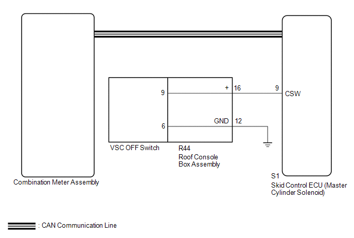
WIRING DIAGRAM
CAUTION / NOTICE / HINT
NOTICE:
- When replacing the skid control ECU (master cylinder solenoid), perform
calibration (See page
.gif) ).
). - Inspect the fuses for circuits related to this system before performing the following inspection procedure.
- As there may be malfunctions in the transfer system related to when the transfer operates in L4, check the transfer system first.
PROCEDURE
|
1. |
CHECK SFI SYSTEM |
(a) Check if SFI system DTCs are output (See page
).
|
Result |
Proceed to |
|---|---|
|
DTCs are not output |
A |
|
DTCs are output |
B |
| B | .gif) |
GO TO SFI SYSTEM (DIAGNOSTIC TROUBLE CODE CHART) |
|
.gif)
|
2. |
CHECK CAN COMMUNICATION SYSTEM |
(a) Turn the ignition switch off.
(b) Connect the Techstream to the DLC3.
(c) Turn the ignition switch to ON.
(d) Turn the Techstream on.
(e) Select CAN Bus Check from the System Selection Menu screen and follow the
prompts on the screen to inspect the CAN bus (See page
).
OK:
CAN Bus Check indicates no malfunctions in CAN communication.
| NG | |
GO TO CAN COMMUNICATION SYSTEM (HOW TO PROCEED WITH TROUBLESHOOTING) |
|
|
3. |
INSPECT SKID CONTROL ECU (CSW TERMINAL) |
(a) Disconnect the S1 skid control ECU (master cylinder solenoid) connector.
|
(b) Measure the resistance according to the value(s) in the table below. Standard Resistance:
|
|
.png)
(c) Reconnect the S1 skid control ECU (master cylinder solenoid) connector.
Result|
Result |
Proceed to |
|---|---|
|
OK (w/ Rear Differential Lock) |
A |
|
OK (w/o Rear Differential Lock) |
B |
|
NG |
C |
| B | |
GO TO STEP 5 |
| C | |
GO TO STEP 6 |
|
|
4. |
CHECK FOR DIFFERENTIAL SYSTEM |
(a) Reconnect the S1 skid control ECU (master cylinder solenoid) connector.
(b) Connect the Techstream to the DLC3.
(c) Turn the ignition switch to ON.
(d) Turn the Techstream on.
(e) Enter the following menus: Powertrain / Four Wheel Drive / Trouble Codes.
(f) Check for DTCs.
Result|
Result |
Proceed to |
|---|---|
|
DTCs are not output |
A |
|
DTCs are output |
B |
| B | |
GO TO DIFFERENTIAL SYSTEM (DIAGNOSTIC TROUBLE CODE CHART) |
|
|
5. |
READ VALUE USING TECHSTREAM (TRAC/VSC OFF MODE) |
(a) Turn the ignition switch off.
(b) Connect the Techstream to the DLC3.
(c) Turn the ignition switch to ON.
(d) Turn the Techstream on.
(e) Enter the following menus: Chassis / ABS/VSC/TRAC / Data List.
ABS/VSC/TRAC|
Tester Display |
Test Part |
Control Range |
Diagnostic Note |
|---|---|---|---|
|
TRAC/VSC Off Mode |
TRAC/VSC off mode/ Normal, TRC OFF, Unknown or VSC OFF |
Normal: Normal mode TRC OFF: TRAC OFF mode VSC OFF: VSC OFF mode |
- |
(f) Check that the mode display changes according to VSC OFF switch operation.
OK:
Display changes according to switch operation.
| OK | |
GO TO METER / GAUGE SYSTEM |
| NG | |
REPLACE MASTER CYLINDER SOLENOID |
|
6. |
INSPECT VSC OFF SWITCH |
(a) Remove the VSC OFF switch (See page ).
(b) Inspect the VSC OFF switch (See page ).
| NG | |
REPLACE VSC OFF SWITCH |
|
|
7. |
INSPECT ROOF CONSOLE BOX ASSEMBLY |
(a) Remove the roof console box assembly.
- for Double Cab: (See page
)
- for Access Cab: (See page
)
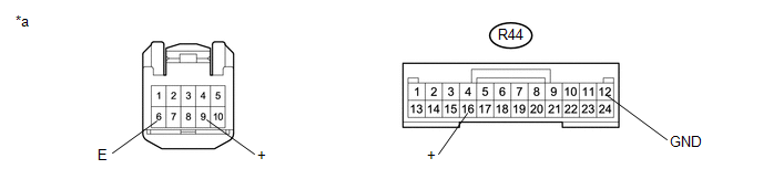 Text in Illustration
|
*a |
Component without harness connected (Roof Console Box Assembly) |
- |
- |
(b) Measure the resistance according the value(s) in the table below.
Standard Resistance:
|
Tester Connection |
Condition |
Specified Condition |
|---|---|---|
|
R44-16 (+) - 9 |
Always |
Below 1 Ω |
|
R44-12 (GND) - 6 (E) |
Always |
Below 1 Ω |
|
Result |
Proceed to |
|---|---|
|
OK |
A |
|
NG (for Double Cab) |
B |
|
NG (for Access Cab) |
C |
| A | |
REPAIR OR REPLACE HARNESS OR CONNECTOR (MASTER CYLINDER SOLENOID - ROOF CONSOLE BOX ASSEMBLY) |
| B | |
REPLACE ROOF CONSOLE BOX ASSEMBLY |
| C | |
REPLACE ROOF CONSOLE BOX ASSEMBLY |
 TRAC OFF Indicator Light does not Come ON
DESCRIPTION
Refer to TRAC OFF Indicator Light Remains ON (See page
).
WIRING DIAGRAM
Refer to TRAC OFF Indicator Light Remains ON (See page
).
CAUTION / NOTICE / HINT
NOTICE:
When re ...
 VSC OFF Indicator Light Remains ON
DESCRIPTION
In 2WD mode:
Operation of the VSC OFF switch changes the vehicle between normal mode,
TRAC OFF mode (AUTO LSD mode) and VSC OFF mode. During normal mode, pressing
the VS ...
Other materials:
Network Gateway Ecu
Components
COMPONENTS
ILLUSTRATION
Installation
INSTALLATION
PROCEDURE
1. INSTALL NETWORK GATEWAY ECU
(a) Install the network gateway ECU with the bolt.
Torque:
3.0 N·m {31 kgf·cm, 27 in·lbf}
(b) Connect the connector.
2. INSTALL LOWER INSTRUMENT PANEL ASSEMBLY
(See page )
R ...
Installation
INSTALLATION
CAUTION / NOTICE / HINT
HINT:
Use the same procedures for the RH side and LH side.
The procedures listed below are for the LH side.
When installing a roof drip side moulding clip, heat the vehicle body
and clip using a heat light.
When installing the moulding, ...
Power outlets (12 VDC)
Please use as a power supply for electronic goods that use less than 12 VDC/10
A (power consumption of 120 W).
When using electronic goods, make sure that the power consumption of all the
connected power outlets is less than 120 W.
■The power outlets can be used when
The engine switch ...
